CAN - Controller Area Network
In the ECU in the car there lived CAN.
1. Prologue
1.0 CAN ID Basic
1.1. Concerning CAN
자동차 내부 통신을 위해 가장 많이 사용되는 CAN 프로토콜에 대해서 배울 것이다.
우선 CAN 프로토콜이 만들어지기 전의 상황을 간단하게 살펴보자.
초기의 자동차는 엔진의 구동부터 바퀴의 회전까지 모든 과정이 기계적인 움직임에 의존했다. 그러나 자동차의 성능(출력, 연비 향상) 등의 이유로 제어를 전자적으로 하게 되면서 ECU(전자 제어 장치, Electronic Control Unit)가 도입되었다. 이때까지는 각 부품 별로만 통신이 필요했고 센서와 ECU 간에 Point-to-point(wiki) 이나 mesh(wiki) network 방식으로 통신했다.
자동차가 발전하면서 안전성이나 편의성 등의 요구가 증가했고 전자 제어가 필요한 부품들이 더욱 많아졌다. 이에 따라 통신해야할 데이터의 양도 늘어났고, ECU 끼리의 통신도 빈번해졌다. 기존의 Point-to-point 방식으로 통신을 하려면 모든 ECU 사이에 통신선을 놓아야했기 때문에 ECU가 늘어날수록 차량의 무게가 점점 더 무거워지는 문제가 발생했다. 따라서 무게를 크게 증가시키지 않으면서 여러 ECU 사이의 통신을 원활하게 할수 있는 통신 방식이 필요했다.
이러한 요구에 BOSCH는 새로운 통신 방식을 개발했고 그 통신방식이 Controller Area Network(CAN)이다.
1.1. Concerning Communication
CAN에 들어가기 앞서 통신에 대해서 이해해보고 CAN과 관련된 기초 지식에 대해서 알아보자.
What is Communication
우선 통신은 뭘까? 통신을 한다는 것은 개체간에 정보를 전달하는 과정이다. 통신은 다양한 형태로 이루어질수 있다. 예를 들면 사람들끼리 대화하는 것이나 인터넷 쇼핑을 하기 위해 특정 웹사이트에 접속하는 것이 있다.
통신을 하기 위해선 여러가지 요소들이 필요한데 이를 몇가지 정리해보면 다음과 같이 나타낼수 있다.
- 메세지(message): 전달하려는 정보. ex: 쇼핑물 상품
- 송신자(sender): 데이터를 보내는 주체. ex. 쇼핑몰 서버
- 수신자(receiver): 데이터를 받는 주체. ex. 유저
- 전송 매체(Medium): 데이터를 전달하는 물리적 경로. ex. 전선
- 프로토콜(Protocol): 통신의 규칙과 절차 ex. TCP/IP
요소들 중에 다른 것들도 중요하지만 프로토콜이 특히 중요하다고 생각한다. 통신을 위한 주체들이 본인의 데이터만을 보내려고하면 충돌이 자주 일어나게 되어 통신이 불가능 해질 것이다.
또 다른 예로 특정 주제에 대해서 사람들끼리 토론을 한다고 해보자. 토론의 참가자들은 본인의 의견(message)을 주장할때 화자(sender)가 되고 반대 진영의 사람들은 청자(receiver)가 된다.
이때 규칙(protocol)에 따라 토론의 양상이 달라질 것이다. 예를 들면 목소리가 큰사람이 발언권을 갖는 다는 규칙이 있으면 시간이 지날수록 모두 화자가 되어 버려 모든 사람이 소리를 질러 무슨 이야기를 하는지 모를 수준이 될 수 있다. 다른 규칙으로 중재자에게 발언권을 얻은 사람만 이야기 할수 있다고 한다면 뜻을 굽히진 않아도 이야기는 계속 이어지는 상황이 만들어 질 것이다.
이렇듯 규칙에 있어선 정답이 없다. 따라서 다양한 기기와 네트워크가 원활하게 협력할 수 있는 효과적인 프로토콜을 찾아야한다.
Serial & Parallel Communication
통신 방식에 대해서도 몇가지 알아보자.
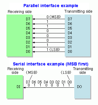
위 그림은 데이터를 보내는 두 방식을 나타낸다. 병렬 통신(위), 직렬 통신(아래)
그림에서 볼 수 있듯 병렬 통신은 연결한 선 만큼 비트를 한번에 보낼 수 있고, 직렬 통신은 한 선에 비트를 순차적으로 보낸다.
- 직렬 통신에서의 순차적인 비트를 비트스트림(bitstream, wiki)이라고 한다.
일반적으로 속도는 병렬 통신이 빠르다. 클럭의 한 주기에 비트 하나를 보낼수 있는 데이터 선이 있다고 해보자. 병렬 통신은 데이터 선을 연결한 만큼 한 주기에 배수로 보낼수 있다. 병렬 통신을 위해 8개의 데이터선이 있다고하면 한 주기당 8bit를 보낼수 있다. 직렬 통신에선 하나의 데이터 선만 사용하므로 한 주기당 1bit를 보낼수 있다. 이런 환경에서 32bit 데이터를 각각 보낸다고하면 8bit 병렬 통신은 4 주기에, 직렬통신은 32 주기에 통신을 끝낼 수 있다.
속도만 보면 좋아보이지만 병렬 통신에도 단점이 존재한다. 병렬 통신은 데이터 라인의 개수만큼 전선의 무게가 많이 늘어난다. 그리고 전선은 거리에 따라 노이즈가 많이 발생해서 길이를 길게 만들수도 없고 병렬로 놓인 전선끼리의 전자기 간섭으로 오류가 많이 발생한다.
- 또한 고속에서 사용하면 타이밍이 어긋나서 데이터를 잘못 읽는 문제도 있다고 한다.(timing skew, 출처: https://powerdeng.tistory.com/11)
비교 정리 (Click)
| 특성 | 직렬 통신 (Serial Communication) | 병렬 통신 (Parallel Communication) |
|---|---|---|
| 전송 방식 | 데이터를 한 번에 한 비트씩 순차적으로 전송 | 여러 비트를 동시에 전송 |
| 배선 구조 | 간단 (송신선과 수신선만 필요) | 복잡 (여러 개의 데이터 라인 필요) |
| 전송 속도 | 비교적 느림 | 매우 빠름 |
| 장거리 통신 | 유리 (신호 손실이 적고 신뢰성 높음) | 부적합 (신호 손실과 간섭 문제) |
| 전자기 간섭 | 적음 (전선 수가 적어 간섭이 적음) | 많음 (많은 전선으로 인해 간섭 발생 가능) |
| 비용 | 저렴 (배선이 간단하고 설치 비용이 낮음) | 높음 (복잡한 배선 구조로 설치 비용 증가) |
| 신뢰성 | 높음 (간단한 구조와 간섭 감소로 신뢰성 높음) | 낮음 (복잡한 구조와 간섭 문제) |
| 예시 |
USB (Universal Serial Bus) RS-232 (컴퓨터와 주변기기 간의 직렬 통신) I2C (칩 간의 저속 직렬 통신) SPI (칩 간의 고속 직렬 통신) |
병렬 프린터 포트 (컴퓨터와 프린터 간의 병렬 통신) IDE (초기 컴퓨터의 하드 드라이브와의 병렬 통신) PCI (컴퓨터 내부의 부품 간 병렬 통신) |
Synchronous & Asynchrounous Communication
몇 가지 통신을 확인해보면 clock 이 들어가는 통신 방식(ex. SPI, i2C)이 있고 들어가지 않는 통신 방식(ex. UART)이 있다. 어떨땐 clock이 필요하고 어떨땐 clock이 필요없는 걸까?
우선 clock 이 왜 필요할까를 먼저 생각해보자. 송신자가 “12345678” 이란 데이터를 보낸다고 해보자. 이때 수신자는 받는 속도에 따라 데이터를 다르게 받아 들일것이다.
- 수신자가 송신자와 같은 속도(1로 가정)로 받는 경우, 송신자가 보낸 데이터 그대로 받아올수 있다. “12345678”
- 수신자가 송신자보다 빠른 속도(2로 가정)로 받는 경우, 이전 데이터가 중복되어 들어올 것이다. “1122334455667788”
- 수신자가 송신자보다 느린 속도(0.5로 가정)로 받는 경우, 데이터가 씹혀서 들어올것이다. “1357” or “2468”
이 세가지 예를 보면 1)의 예시만 제대로 된 값을 받을수가 있고 2)는 데이터를 중복값을 제거하는 것과 같이 한 번 더 처리해서 사용해야하고 3)은 데이터가 유실되는 문제를 가지고 있다. 따라서 데이터 송수신 속도가 같아야지만 효율적으로 통신할 수 있고 이렇게 송수신 속도를 같게 하기위해 동기화라는 것이 필요하다.
동기화를 구현하기 위해서 두가지 방식이 존재한다. wiki
- 데이터 신호와 Clock 신호의 통신선을 분리하고 송신자가 보낸 클럭(혹은 외부 클럭)에 동기화를 맞추는 방식을 Synchronous 방식이라고 한다.
- 데이터 신호에서 clock을 뽑아내서 동기를 맞추는 방식을 Asynchrounous 방식이라고 한다.
- 데이터에서 클럭을 뽑아낸다는게 이상해 보일수 있을 것이다. 클럭 신호를 유추한다고 생각하면 된다. 유추하는 방법은 여러가지가 있겠지만 주로 메세지의 첫 시작을 HIGH와 LOW를 번갈아 보내는 걸로 유추할수 있다. 예를 들어 메세지의 첫 시작은 무조건 “010101”을 보낸다고 하자. 수신자가 사용하지 않는 상태에 있다가 데이터가 들어오는 것을 감지할수 있다. 이 때 받은 신호에서 0과 0 혹은 1과 1 사이의 주기를 측정하고 이를 통해 속도를 유추 할 수 있다.
BUS Network (BUS Topology)
일반적인 버스 네트워크에 대해서도 알아보자.
| General BUS | Add a Node in BUS |
|---|---|
|
|
|
우선 버스 네트워크의 특징은 확장에 유리하다.
- 새로운 노드(데이터를 송수신할 수 있는 최소 장치, wiki)를 추가할 때 기존 네트워크에 연결만 하면 된다.
버스 네트워크는 Multi Master Network 이고 노드간 통신은 Half-duplex 방식이다.
- Multi master Network라는 건 어떤 노드든 마스터가 되어 데이터를 보낼수 있다는 것이다. Sinlge Master Multi Slave 가 있을수 있고 이 경우는 한 노드만 마스터가 되고 나머지는 슬레이브가 되어 단방향으로만 데이터 송수신이 가능하다.
- Half-duplex(반이중통신)는 통신의 방향성을 나타낸다. 무전기처럼 양방향으로 통신이 가능하나 동시에 송수신은 불가능 하다. 이 외에도 Full duplex(전이중통신), Simplex(단방향 통신) 등이 있다. wiki
- 즉, BUS 네트워크는 일반적으로 여러 노드가 데이터를 송수신할 수 있고, 한 노드가 데이터를 송신하면 나머지 노드는 데이터를 수신하는 관계가 된다.
여러 노드가 동시에 데이터를 전송해서 데이터를 사용하지 못하는 경우가 생기는데 이를 충돌(collision)이라 한다.
- 이를 해결하기 위해 우선 순위나 Media Access Control(MAC, wiki)를 사용한다.
point-to-point 방식과 비교(Click)
| General BUS | Add a Node in BUS |
|---|---|
|
|
|
point-to-point 방식은 다른 노드와 통신하기 위해서 필요한 노드간에 통신선을 놓아야한다.
- 노드가 많을수록 새로운 노드를 위해 추가되는 통신선의 양이 많아진다.
통신 방식은 Half-Duplex 방식이지만 네트워크가 겹치지 않으므로 여러 노드에서 한 노드로 데이터를 보낼수 있다.
1.2. Concerning CAN
통신에 대해 간략하게 배웠으니 CAN 프로토콜에 대해서 배워보자. CAN은 자동차 산업 분야에 적용하기 위해 고안된 직렬 통신 프로토콜이다.
CAN BUS
CAN도 BUS 구조이다. 지난 챕터에 BUS 네트워크에 대해서 언급했으니 이해하기 쉽게 CAN BUS부터 확인하자.
| General BUS | CAN BUS |
|---|---|
|
|
|
CAN도 일반적인 BUS의 특성을 갖는다.
- 이론적으론 무한한 노드를 연결할 수 있다. 실질적으론 버스 라인의 지연 시간과 전기 부하에 의해 갯수가 제한된다.
- 오래된 CAN Controller와 통신하는 CAN 노드 한정으로 서로 다른 identifier를 가진 노드는 최대 2032($2032 = 2^{11} - 2^4$)개만 연결할수 있다.
- 2.0A 기준 ID bit가 11개이므로 ID가 서로 다른 노드는 $2^{11}$개이다.
- 1980년대 Intel CAN 컨트롤러(82526)는 최상위 7bit가 모두 1이면 안된다고 한다. 이 컨트롤러와 호환을 위해 $2^{11-7}= 2^4$ 개의 ID는 사용하지 못한다.
CAN은 연선 방식(Twisted Pair, wiki)의 와이어를 사용하고 차동 신호 방식(Differential Signaling, wiki)을 사용하여 데이터를 전송한다.
- 연선 방식의 와이어는 잡음(noise)과 간섭(EMI)을 방지한다.
- 두 개의 와이어는 각각 CAN-H와 CAN-L으로 사용하고 두 개의 와이어 사이의 전압 차이를 이용해 신호를 전달한다.
- Dominant(우성): CAN-H와 CAN-L이 전위차가 있는 경우를 뜻하며 논리적 레벨로 0이 된다. (실질적으론 이정도이다. CAN-H - CAN-L > 0.9V)
- Reccesive(열성): CAN-H와 CAN-L이 전위차가 없는 경우를 뜻하며 논리적 레벨로 1이 된다. (실질적으론 이정도이다. CAN-H - CAN-L < 0.5V)
- Dominant, Reccesive각 논리 레벨로 0,1인 이유는 CAN BUS가 Wired AND Connection이기 때문에 (0이 존재하면 항상 0이 나오므로) 0이 항상 우세하다.
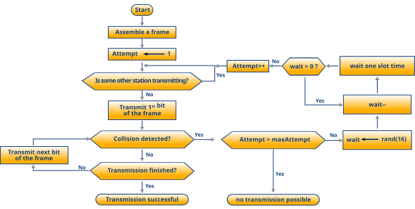
충돌을 해결하기 위해 CSMA/CD(Carrier Sense Multiple Access / Collision Detection)와 AMP(Arbitration on Message Priority) 방식을 사용한다.
- CSMA/CD는 충돌이 감지 되는 즉시 전송을 종료하고 충돌을 알린뒤 랜덤한 시간 뒤에 다시 신호를 보내는 방식이다.
(출처: csma/cd wikipedia)- CSMA wiki
- CSMA/CD wiki
- AMP는 충돌이 발생한 경우 우선 순위가 높은 메세지(중요한 메세지)가 먼저 보내지고 충돌난 메세지는 이후에 다시 보내게 된다.
CAN Layer
CAN 통신의 기능들을 쉽게 이해하기 위해 CAN Layer에 대해서 살펴보자.
OSI 모델과 CAN Layer를 비교하면 명확하게 이해할 수 있겠지만 양이 너무 방대하니 CAN의 계층을 간단히 요약하자면 다음과 같다.
- Physical Layer (물리 계층)
- PDU(전송단위): Bit, symbol
- OSI 모델: 전기적 신호를 전송하고 물리적 연결을 설정하며, 데이터 전송 매체를 정의한다.
- CAN: CAN의 물리 계층은 서로 다른 노드 간에 전기적 신호를 전달하는 역할을 한다. 외부 전기적 간섭에 강한 내성을 갖는다.
- Standard CAN:
- Signal Level and Bit Representation
- Transmission Medium
- Extended CAN:
- Bit Encoding/Decoding
- Bit Timing
- Synchronization
- Data Link Layer (데이터 링크 계층)
- PDU(전송단위): Frame(wiki)
- Frame 은 일반적으로 동기화 비트, 데이터(페이로드), 프레임 검사 시퀀스로 이루어져있고, interframe gap을 통해 다음 프레임과 구분된다.
- OSI 모델: 데이터 프레이밍, 물리 주소 지정, 오류 검출 및 수정, 흐름 제어를 담당한다.
- CAN: CAN 메시지 프레임은 이 계층에서 처리되며, 메시지의 우선순위를 결정하고 충돌을 방지하는 역할을 한다.
- Standard CAN
- Transfer Layer:
- Fault Confinement: 단기적인 오류(short distubances)와 영구적인 오류(permanent failures)를 구별한다. 영구적인 결함이면 사용못하게 한다.(switch off)
- Error Detection: 모니터링(송신기측 비트레벨과 버스에서 감지된 비트레벨 비교), CRC, Bit Stuffing, Message Frame Check 등을 통해 오류를 감지한다.
- Error Signaling: 메시지가 손상된 경우 전송이 중단 되고 재전송된다.
- Message Validation: 메세지가 올바른지 확인한다.
- Acknowledgment: 메세지를 수신했다고 알린다.
- Arbitration: 버스에서의 충돌은 식별자를 사용해서 비트 단위로 중재한다. 동일 식별자를 가진 데이터프레임과 원격 프레임은 데이터 프레임이 우선된다.
- Message Framing: 메세지 프레임 단위로 인식할수 있도록 묶고 푸는 작업을 한다.(Encapsulation/Decapsulation)
- Transfer Rate and Timing
- Object Layer:
- Message Filtering: 식별자를 읽고 데이터를 사용할지 선택한다.
- Message and Status Handling: 메시지의 전송, 수신, 처리 상태를 관리해서 메세지 상태를 추적하고 오류를 감시한다.
- Transfer Layer:
- Extended CAN
- Medium Access Control sublayer:
- Data Encapsulation(Decapsulation): 메세지 프레임 단위로 인식할수 있도록 묶고 푸는 작업을 한다. (네트워크 레이어 <-> 데이터링크 레이어)
- Frame Coding(Stuffing, Destuffing): 연속된 비트에 대해 반대 비트를 넣어주는 작업. 수신측에선 빼는 작업을 한다.
- Medium Access Management: 네트워크 매체(버스)를 사용하는 여러 노드 간의 충돌을 방지하고, 효율적인 통신을 보장한다. (arbitration, CSMA/DA)
- Error Detection: 모니터링(송신기측 비트레벨과 버스에서 감지된 비트레벨 비교), CRC, Bit Stuffing, Message Frame Check 등을 통해 오류를 감지한다.
- Error Signaling: 메시지가 손상된 경우 전송이 중단 되고 재전송된다
- Acknoledgment: 메세지를 수신했다고 알린다.
- Serialization/Deserializaion: 송신 프레임을 보낼수 있는 비트단위로 쪼개고, 수신된 비트를 프레임으로 합치는 작업을 한다.(데이터링크 레이어 <-> 물리 레이어)
- Logical Link Control sublayer:
- Acceptance Filtering: 식별자를 읽고 데이터를 사용할지 선택한다.
- Overload Notification: 네트워크에서 프레임 전송이 지연되도록 신호를 보낸다. CAN 버스의 과부하를 방지하거나 다른 중요한 작업을 처리하기 위해 사용된다.
- Recovery Management: 오류가 감지 되지 않은 경우 그 다음 메세지가 시작되도록 복구한다.
- Medium Access Control sublayer:
- PDU(전송단위): Frame(wiki)
- Network Layer 이상 (네트워크 계층 이상)
- OSI 모델: 논리적 주소 지정, 경로 설정, 데이터 전송의 신뢰성을 보장, 통신 세션 관리, 데이터 형식 변환 및 최종 사용자와의 상호작용을 담당한다.
- CAN: 네트워크 계층 이상의 기능은 다른 프로토콜(예: XCP, UDS on CAN 등)을 통해 구현될 수 있다.
용어가 어렵기도 하고, 계층에 대해서 설명하다가 갑자기 Standard CAN과 Extended CAN이 나와서 혼란스러울 수도 있다. 그래도 CAN의 기능들이 어떤게 있는지 어느정도 파악했으니 넘어가도록하자.
- Standard CAN과 Extended CAN은 식별자(ID)비트의 수로 인한 차이를 제외하고선 용어만 다르게 정의되어있을뿐 크게 다르지 않다. 자세한 내용은 CAN Message 챕터에서 확인하자.
- 용어에 대한 설명들도 이후 챕터에서 자세히 설명하도록 하겠다.
OSI 모델과 CAN의 비교(Click)
OSI 모델(wiki)은 한 번 정도는 읽어보고 이해할 필요가 있다. OSI 모델(Open Systems Interconnection Reference Model)은 표준 프로토콜을 사용하여 다양한 통신 시스템이 통신할 수 있도록 국제표준화기구에서 만든 개념 모델이다. OSI 모델은 통신 시스템을 7개의 계층으로 나누어 설명하는데, 이를 통해 각 계층의 역할과 기능을 명확히 할 수 있다.
특히 봐야할 것은 Layer 별 PDU이고 CAN은 Datalink Layer 아래에만 있다는 것이다.
| OSI 7 Layers | Protocol Data Unit (PDU) | CAN 2.0 Part A Standard CAN |
CAN 2.0 Part B Extended CAN |
|---|---|---|---|
| Application Layer | Data | ||
| Presentation Layer | |||
| Session Layer | |||
| Transport Layer | Segment | ||
| Network Layer | Packet | ||
| Data Link Layer | Frame |
Object Layer - Message Filtering - Message and Status Handling |
Logical Link Control sublayer - Acceptance Filtering - Overload Notification - Recovery Management |
|
Transfer Layer - Fault Confinement - Error Detection and Signalling - Message Validation - Acknowledgment - Arbitration - Message Framing - Transfer Rate and Timing |
Medium Access Control sublayer - Data Encapsulation / Decapsulation - Frame Coding (Stuffing / Destuffing) - Medium Access Management - Error Detection - Error Signalling - Acknowledgment - Serialization / Deserialization |
||
| Physical Layer | Bit |
Physical Layer - Signal Level and Bit Representation - Transmission Medium |
Physical Layer - Bit Encoding/Decoding - Bit Timing - Synchronization |
CAN Message
이제 CAN 메시지의 구조에 대해 알아보자.
CAN 메시지는 CAN 네트워크에서 데이터를 주고받는 기본 단위이다. CAN 메시지는 총 7개의 다른 필드로 구성되어있다. 필드 내의 비트를 설정해서 메세지 포맷과 프레임 타입을 결정할수 있다.
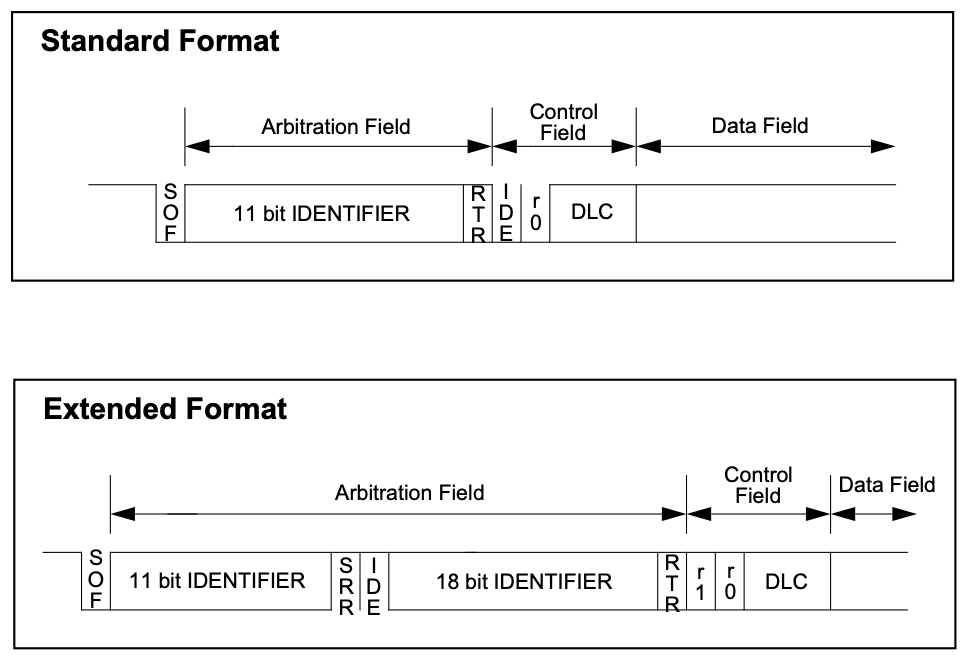
메세지 포맷은 Standard CAN과 Extended CAN으로 나눌 수 있다.
- Standard CAN(CAN 2.0A)은 11 bit의 식별자 비트를 갖고 있어서 최대 2,048의 고유한 메세지 ID를 가질수 있다. CAN의 초기 스펙 (CAN 1.0)과 호환되도록 설계되었다.
- Extended CAN(CAN 2.0B)은 29 bit의 식별자 비트를 갖고 있어서 최대 536,870,912개의 고유한 메세지 ID를 가질수 있다. Standard CAN과의 호환성을 위해 설계된 부분이 있다.
- Extended ID: Standard 와 호환을 위해 11+18 bit로 쪼개어 사용한다. 앞 부분의 11bit ID가 같은 경우(Standard CAN 과 Extended CAN 이 충돌하는 경우) Extended CAN의 SSR 비트로 인해 Standard CAN이 항상 우선된다.
- Standard Control Field의 R1과 같은 위치에 Extended Arbitration Field의 IDE가 존재하고 서로 반대 비트를 가진다. R1: bit “0”, IDE: bit “1”
※ Controller 호환성 (Click)
Standard CAN(CAN 2.0A) Controller 는 standard CAN 포맷 방식의 메시지만 송수신이 가능하다.
- CAN 2.0 이전 사양(1.x)도 서로 통신할 수 있다
- Extended CAN 메시지를 수신하면 데이터를 무시한다
Extended CAN(CAN 2.0B) Controller 는 Standard, Extended 메시지 포맷 모두 송수신 가능하다.
- 만약 데이터 프레임이 standard와 extended 모두 같은 Base ID (첫 11 비트)를 가지면 Standard 데이터 프레임으로 인식한다. (SRR은 RTR 1로 인식)
- 요즘은 대부분 CAN2.0B 컨트롤러를 사용한다.
메세지 프레임은 총 4가지가 있다.
- Data Frame: 가장 기본적인 메세지 프레임이다. 데이터를 전달하기 위해 사용한다.
- Remote Frame: 재전송을 요청할때 사용한다.
- Error Frame: CAN 네트워크에서 오류를 감지했을 때 사용한다. CAN 노드는 데이터 전송 중 오류를 실시간으로 모니터링하며, 오류가 발생하면 즉시 에러 프레임을 전송하여 네트워크의 다른 노드에 알린다
- Overload Frame: 프레임 사이에 추가 딜레이를 요청할때 사용한다. 주로 네트워크의 노드가 데이터 처리 속도를 따라잡지 못할 때 사용된다.
각각의 메세지 프레임을 살펴보면서 필드와 비트가 어떤 의미인지 확인해보자
Data Frame
데이터를 전달하기 위한 메세지 프레임이다.
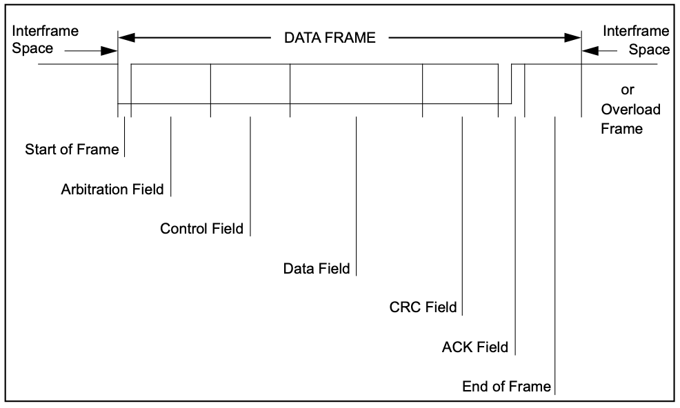
- 시작 프레임(Start of Frame, SOF): 데이터 프레임의 시작을 나타낸다.
- 1비트의 ‘Dominant’ 신호이다. (0b0)
- Arbitration Field (중재 필드): 식별자를 포함하고 있으며 REMOTE 프레임과 구분하기 위한 비트가 있다. 식별자는 메시지의 우선순위를 결정하고 네트워크 내에서 메시지를 구별하는 데 사용된다.
- Standard CAN: 11비트 식별자, RTR (IDE=0b0, r0 비트, Control Field)
- Extended CAN: 11비트 기본 식별자, SRR, IDE=1, RTR, 18비트 확장 식별자
- 제어 필드(Control Field): 데이터 길이 코드(DLC)를 포함하며, 전송되는 데이터의 길이를 나타낸다.
- Standard CAN: IDE = 0b0, r0 비트, DLC (4비트)
- Extended CAN: r1, r0 예약 비트 + DLC (4비트)
- 데이터 필드(Data Field): 실제 전송되는 데이터가 포함되며, 최대 8바이트의 데이터를 담을 수 있다. 이는 CAN 메시지의 핵심 부분으로, 필요한 정보를 전송하는 역할을 한다.
- CRC 필드(CRC Field): 오류 검출을 위한 사이클릭 중복 검사(CRC) 코드를 포함한다. 데이터 전송 중 발생할 수 있는 오류를 검출하여 데이터의 무결성을 보장한다.
- ACK 필드(Acknowledgement Field): 메시지의 수신을 확인하는 비트이다. 수신 노드는 이 필드를 통해 메시지를 성공적으로 수신했음을 송신 노드에 알린다.
- 종료 프레임(End of Frame, EOF): 프레임의 끝을 나타낸다.
- 7비트의 ‘Recessive’ 신호이다. (0b1111111)
비교 정리 (Click)
| Bitfield | Standard CAN | Extended CAN | |
|---|---|---|---|
| Start Of Frame (SOF) |
1bit, bit "0" 메시지 프레임의 맨 앞에 위치함 |
Standard CAN 과 동일 | |
| Arbitration Field | ID (11-bit) | Base ID (11-bit) | |
|
RTR (1-bit), bit "0" 해당 메시지가 데이터 프레임이라는 것을 가리킴 - bit "1": 원격전송 요청(RTR : Remote Transmission Request)을 의미함. |
SSR (Substitute Remote Request, 1-bit) bit "1" |
||
| IDE (1-bit), bit "1" | |||
| Extended ID (18-bit) | |||
|
RTR (1-bit), bit "0" 해당 메시지가 데이터 프레임이라는 것을 가리킴 |
|||
| Control Field | Reserved 1, bit "0"(IDE) | Reserved 1, bit "0" | |
| Reserved 0, bit "0" | Reserved 0, bit "0" | ||
| Data Length Code (4-bit) 0~8 byte 전송 가능 |
Standard CAN 과 동일 | ||
| Data Field |
한 노드로부터 다른 노드로 전하고자 하는 데이터를 포함함. DLC에 맞는 길이로 구성됨 |
||
| CRC Field | CRC Sequence(15-bit) CRC polynomial = 0b_1100_0101_1001_1001 |
Standard CAN 과 동일 | |
| CRC Delimiter (1-bit), bit "1" | Standard CAN 과 동일 | ||
| ACKnowledge Field |
ACK Slot (1-bit), bit "0" 다른 노드가 메시지를 성공적으로 수신하면 bit "1"로 변경함 |
Standard CAN 과 동일 | |
| ACK delimiter(1-bit), bit "1" | Standard CAN 과 동일 | ||
| End Of Frame Field (EOF) |
7-bit, 7bit 모두 "1" | Standard CAN 과 동일 | |
심화내용: Interframe Spacing(Click)
Interframe Spacing
메세지 프레임을 구분하기 위한 장치
- Data Frame 및 Remote Frame은 interframe spacing을 통해 이전 프레임과 구분된다.
- Overload Frame 및 Error Frame은 해당 비트필드로 구분되지 않는다.
| Bitfield | Standard CAN | Extended CAN |
|---|---|---|
| Intermission |
3 'recessive' bit INTERMISSION 중에는 어떤 스테이션도 DATA FRAME 또는 REMOTE FRAME의 전송을 시작할 수 없음 OVERLOAD 조건을 알리는 것 외엔 아무것도 할 수 없음 |
|
| Bus Idle |
BUS IDLE period는 임의의 길이일 수 있음 전송할 내용이 있는 모든 스테이션에서 버스에 액세스할 수 있음 다른 메시지 전송 중에 전송 보류 중인 메시지는 INTERMISSION 다음의 첫 번째 비트에서 시작됨 버스에서 'Dominant' 비트 감지는 프레임 시작으로 해석됨 |
|
| Suspend Transmission |
'error passive' 스테이션의 경우에만 포함됨 'error passive' 스테이션은 메시지를 전송한 후 추가 메시지 전송을 시작하거나 버스가 Idle상태임을 인식하기 전에 INTERMISSION 다음에 8개의 'recessive' 비트를 보냄 그 동안 다른 스테이션에 의해 전송이 시작되면 스테이션은 이 메시지의 수신자가 됨 |
|
해당 프레임이 끝나면 CAN 버스라인은 IDLE 상태로 인식된다.
심화내용: Remote Frame(Click)
Remote Frame
재전송을 요청하는 프레임이다.
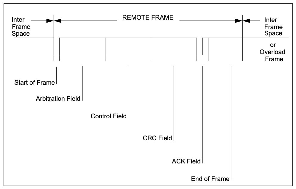
전체적으로 Data Frame과 비슷하지만 RTR 비트가 1이어야하고 데이터 필드가 없다.
| Bitfield | Standard CAN | Extended CAN |
|---|---|---|
| Start Of Frame (SOF) |
1bit, bit "0" 메시지 프레임의 맨 앞에 위치함 |
Standard CAN 과 동일 |
| Arbitration Field | ID (11-bit) | Base ID (11-bit) |
|
RTR (1-bit), bit "0" 해당 메시지가 데이터 프레임이라는 것을 가리킴 - bit "1": 원격전송 요청(RTR : Remote Transmission Request)을 의미함. |
SSR (Substitute Remote Request, 1-bit) bit "1" |
|
| IDE (1-bit), bit "1" | ||
| Extended ID (18-bit) | ||
|
RTR (1-bit), bit "0" 해당 메시지가 데이터 프레임이라는 것을 가리킴 |
||
| Control Field | Reserved 1, bit "0"(IDE) | Reserved 1, bit "0" |
| Reserved 0, bit "0" | Reserved 0, bit "0" | |
| Data Length Code (4-bit) 0~8 byte 전송 가능 |
Standard CAN 과 동일 | |
| CRC Field | CRC Sequence(15-bit) CRC polynomial = 0b_1100_0101_1001_1001 |
Standard CAN 과 동일 |
| CRC Delimiter (1-bit), bit "1" | Standard CAN 과 동일 | |
| ACKnowledge Field |
ACK Slot (1-bit), bit "0" 다른 노드가 메시지를 성공적으로 수신하면 bit "1"로 변경함 |
Standard CAN 과 동일 |
| ACK delimiter(1-bit), bit "1" | Standard CAN 과 동일 | |
| End Of Frame Field (EOF) |
7-bit, 7bit 모두 "1" | Standard CAN 과 동일 |
심화내용: Error Frame(Click)
Error Frame
에러 프레임은 CAN 네트워크에서 오류를 감지하고 처리하기 위해 사용된다. CAN 노드는 데이터 전송 중 오류를 실시간으로 모니터링하며, 오류가 발생하면 즉시 에러 프레임을 전송하여 네트워크의 다른 노드에 알린다. 에러 프레임이 전송되면, 네트워크의 모든 노드는 현재 전송 중인 메시지를 무시하고 버린다. 그런 다음, 문제가 있는 메시지는 자동으로 재전송된다.
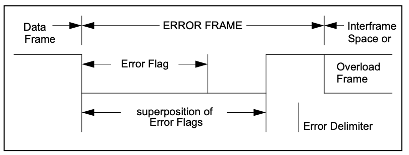
에러 프레임은 두 가지 부분으로 구성된다
- 에러 플래그 (Error Flag)
- 활성 에러 플래그 (Active Error Flag): 0b000000
- 이 플래그는 에러 액티브 상태(Active Error State)에 있는 노드에서 전송된다. 비트 스터핑 위반을 통해 오류 발생을 네트워크 상의 다른 노드에 알린다.
- 수동 에러 플래그 (Passive Error Flag): 0b111111
- 이 플래그는 에러 패시브 상태(Passive Error State)에 있는 노드에서 전송된다. 에러 패시브 상태는 노드가 일정 수준 이상의 오류를 경험했음을 나타내며, 네트워크의 다른 노드들에게 덜 방해가 되도록 설계되었다. 네트워크 상의 다른 노드들이 6비트의 연속된 recessive 비트를 감지하면 수동 에러 플래그가 완성된 것으로 간주된다.
- 에러 딜리미터 (Error Delimiter)
- 0b11111111 (8 ’recessive’ bits)
- 에러 플래그 뒤에 오고 에러 프레임의 끝을 나타낸다. 이는 네트워크가 에러 프레임의 종료를 인식하고 다음 데이터 전송을 준비할 수 있도록 한다.
| Error Flag |
Active Error: Passive Error: 에러를 감지한 'error active' 스테이션은 active error flag를 전송함. SOF부터 CRC까지 모든 필드에 적용되는 비트 스터핑을 위반해서 다른 스테이션에 알림. 6개의 동일한 비트가 감지되면 PASSIVE ERROR FLAG가 완료됨. |
|
심화내용: Overload Frame(Click)
Overload Frame
오버로드 프레임은 네트워크의 노드가 데이터 처리 속도를 따라잡지 못할 때 사용된다. 오버로드 프레임은 수신 측 노드가 과부하 상태임을 나타내어 송신 측이 데이터를 전송하기 전에 잠시 대기하도록 한다. 이는 네트워크의 안정성을 유지하고 데이터 손실을 방지하는 데 도움이 된다.
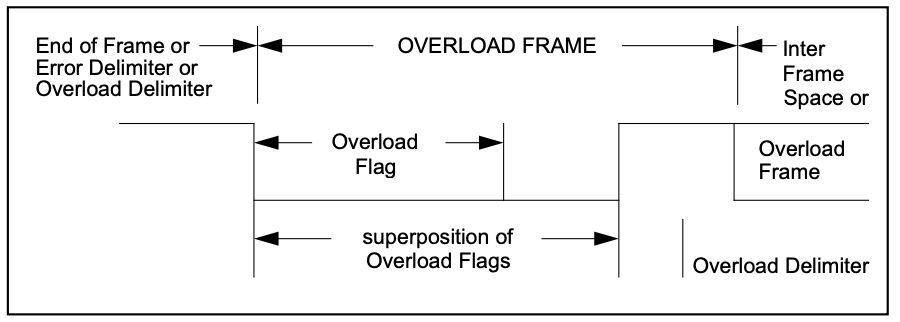
오버로드 프레임은 두 가지 부분으로 구성된다
- 오버로드 플래그 (Overload Flag):
- 0b000000
- 이 플래그는 비트 스터핑 규칙을 위반하여 네트워크 상의 다른 노드들이 이를 감지할 수 있도록 한다.
- 오버로드 플래그는 최대 두 개의 연속된 프레임으로 전송될 수 있다.
- 오버로드 딜리미터 (Overload Delimiter):
- 0b11111111
- 오버로드 플래그 뒤에 오며 오버로드 프레임의 끝을 나타낸다.
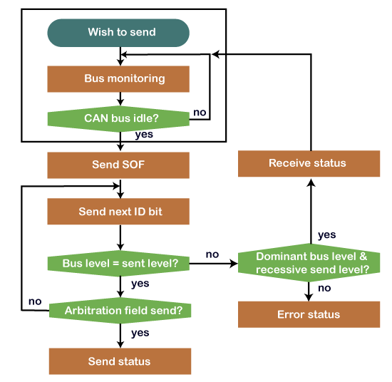
CAN 메세지 송수신 과정
메세지 전송 과정에 대해서 알아보자
 출처: https://www.javatpoint.com/can-protocol
- 메시지 송신 전에 CAN 버스 라인이 사용 중인지 파악한다.
- 버스가 유휴(IDLE) 상태일 때만 메시지를 전송할 수 있다.
- 사용 중이지 않으면 메세지를 보내고 사용 중이면 기다린다.
- 여러 노드가 메세지를 송신할수 있다. 이 경우 메세지가 충돌날 수 있지만 우선순위가 높은 한 메세지만 남고 나머지 노드는 대기한다.
- 데이터가 전송되는 동안 에러가 감지되면 에러 메세지를 전송하고 해당 메세지는 폐기한다.
- 메세지를 수신한 모든 노드는 ID를 확인해서 필요한 메세지만 받고 나머지는 무시한다.
- CAN 네트워크에서 각각의 노드를 식별할 수 있도록 각 노드 마다 유일한 식별자(11bit 또는 29bit)를 갖는다.
- 메시지를 수신한 ECU는 데이터를 처리하고 필요한 경우 응답 메시지를 생성하여 다시 전송한다.
Other things related to CAN 2.0A
Message Validation
메세지가 유효하다고 판단되는 시점
- 송신기: 보내는 메세지의 EOF가 끝날 때까지 오류가 없는 경우
- 수신기: 받는 메세지의 EOF가 마지막 1비트까지 오류가 없는 경우
Coding
Data Frame과 Remote Frame의 SOF 부터 CRC Sequence 까지만 bit stuffing이 사용된다.
- bit stuffing: 연속되는 5개의 동일한 비트가 감지되면 자동으로 반대 비트를 섞어서 보내는 것.
비트스트림은 NRZ(wiki) 방식으로 코딩된다.
- NRZ(Non Return to Zero): 한 비트를 표현할 때 전압을 계속 유지한다.
- RZ(Return to Zero): 한 클럭 내에서 데이터의 전압을 표현하고 다시 0으로 돌아간다.

출처 - wikipedia
Error Handling
Error Detection
- Bit Error: 보낸 비트값이랑 버스에서 모니터링된 값이 다른 때
- Stuff Error: 비트 스터핑이 잘못 되었을 때
- CRC Error: 계산된 CRC 값과 수신된 결과가 다를 때
- Form Error: 고정된 형식의 비트필드에 잘못된 비트가 포함된 때
- Acknowledgment Error: ACK SLOT에서 수신기가 값을 바꾸지 않은 때
(+) 오류들은 같이 뜰 수 있음
Error Signalling
오류를 감지한 노드는 Error Flag를 전송한다.
- Error Active Node: Active Error Flag 전송
- Error Passive Node: Passive Error Flag 전송
Fault Confinement
Fault Confinement 과 관련해서 송수신기는 아래 세 가지 상태 중에 있을 수 있다.
- Error Active
- 버스 통신에 참여할수 있음
- 오류가 감지되면 Active Error Flag 전송함
- Error Passive
- 버스 통신에 참여할수 있음
- 오류가 감지되면 Passive Error Flag 전송함
- 플래그 전송후 추가 전송을 시작하기전 대기함
- Bus Off
- 버스에 어떤 영향도 미칠수 없음.
결함 제한을 위해 모든 버스 장치에 오류 횟수를 저장한다.
- 전송 오류 횟수
- 수신 오류 횟수
이러한 개수는 총 12개의 규칙에 따라 변경된다.
- 자세한 내용은 can 스펙 참조
Other things related to CAN 2.0B
웬만한건 CAN 2.0 A와 겹치므로 Extended CAN에만 있는 내용을 추가했다.
Message Filtering
전체 식별자를 기반으로 필터링된다
- 마스크 레지스터를 사용하여 연결된 수신 버퍼에 매핑할 식별자 그룹을 선택할 수 있다.
- 마스크 레지스터의 모든 비트는 프로그래밍 가능해야 한다. (메시지 필터링을 위해 활성화하거나 비활성화할 수 있다.)
CAN Protocol Variant
High Speed CAN(ISO 11898)
- 1Mbps 이상의 고속 통신이 가능하다.
- Twisted Wire 끝에 120옴 저항이 달린다.
- 노이즈에 강하다.
Low Speed CAN(ISO 11519)
- 125Kbps 까지의 속도로 통신이 가능하다.
- Twisted Wire를 사용하나 한줄이 끊어져도 정상적으로 통신이 된다.
- ECU와 버스 사이에 120옴 저항이 달린다.
1.2. Concerning CAN FD
CAN with Flexible Data-Rate
자동차가 발전하면서 안전성이나 편의성 등의 요구가 증가했고 전자 제어가 필요한 부품들이 더욱 많아졌다. 이에 따라 통신해야할 데이터의 양도 늘어났고, ECU 끼리의 통신도 빈번해졌다. 기존의 Point-to-point 방식으로 통신을 하려면 모든 ECU 사이에 통신선을 놓아야했기 때문에 ECU가 늘어날수록 차량의 무게가 점점 더 무거워지는 문제가 발생했다. 따라서 무게를 크게 증가시키지 않으면서 여러 ECU 사이의 통신을 원활하게 할수 있는 통신 방식이 필요했다.
이러한 요구에 BOSCH는 새로운 통신 방식을 개발했고 그 통신방식이 Controller Area Network(CAN)이다.
1.3. Note on the car industry history
CAN 이전 Mesh 형 토폴로지 사용
- GM사의 캐딜락
1986년 BOSCH, Automotive Serial Controller Area Network 개발
- 벤츠 요구
- 87년 Intel, CAN controller 출시
- 91년 MB CAN 적용 양산 차량(W140) 출시
1991년 CAN 2.0 발표
- part A 11 bit
- part B 29 bit
1993년 ISO CAN 표준 발표
- ISO 11898-1: Data link layer
- ISO 11898-2: 비내결함성 CAN physical layer(고속)
- ISO 11898-3: 내결함성을 위한 CAN physical layer(저속)
- 11519-2
- 95년 11898
1996년 OBD-II 표준 미국 의무화
- 자동차, 경트럭 등
2001년 EOBD 표준 의무화(가솔린)
2004년 EOBD 표준 의무화(디젤)
2012년 Bosch CAN FD 1.0 발표
2018년 CiA CAN XL 개발 시작
- 폭스바겐 요구
2. The First Journey
Communication with CAN
2.1. CAN Communication using TC275 Lite Kit
AURIX Development Studio 에 있는 CAN example 을 사용해서 실제 CAN 통신을 해 볼 것이다.
2.1.1. 준비사항
- Windows 10 컴퓨터(노트북)
- AURIX Development Studio - how-to-setup
- TC275 Lite Kit & User Manual link
- TC27x User Manaul link
- TC27x Data Sheet link
- TC275 iLLD User Manual link
2.2. Analysis of the examples
Example
2.2.1. MULTICAN
MULTICAN_1_KIT_TC275_LK-TR (Link)
- TC275 Lite Kit에 CAN Node를 두 개 만들고, 루프백 모드를 사용해서 서로 통신한다.
- 예제 동작
- Node 0 sends data to Node 1
- if the transmission is successful, an interrupt service routine occurs that turns on LED1.
- Node 1 receives data from Node 0
- if reception is successful, an interrupt service routine occurs. The ISR compares the tx data and rx data and turn on LED2 if they are equal
2.2.1.1. core0_main
Source Code(Click)
int core0_main(void)
{
    IfxCpu_enableInterrupts();

    /* !!WATCHDOG0 AND SAFETY WATCHDOG ARE DISABLED HERE!!
     * Enable the watchdogs and service them periodically if it is required
     */
    IfxScuWdt_disableCpuWatchdog(IfxScuWdt_getCpuWatchdogPassword());
    IfxScuWdt_disableSafetyWatchdog(IfxScuWdt_getSafetyWatchdogPassword());

    /* Wait for CPU sync event */
    IfxCpu_emitEvent(&g_cpuSyncEvent);
    IfxCpu_waitEvent(&g_cpuSyncEvent, 1);

    /* Application code: initialization of MULTICAN, LEDs and the transmission of the CAN message */
    initMultican();
    initLed();
    transmitCanMessage();

    while(1)
    {
    }
    return (1);
}
- 전역 인터럽트 활성화 - CAN TX, RX 될때 Interrupt Service Routine을 사용해야하므로 인터럽트를 활성화한다.
- WDG 비활성화 - 추후 작성
- cpu WDG
- Safety WDG
- Core 동기화
- core0, core1, core2 모두 emit할때까지 기다리고 동기화가 맞춰지면 이후 코드 실행하는 듯 하다.
- CAN 예제 구동시 필요한 코드
- CAN 모듈 초기화
- LED 모듈 초기화
- 메세지 전송
- (꺼지지 않도록) 무한 루프
2.2.1.2. Initialize MultiCAN Module
Source Code(Click)
// 주석 부분 일정 생략
void initMultican(void)
{
    /* ==========================================================================================
     * CAN module configuration and initialization:
     * ==========================================================================================
     */
    IfxMultican_Can_initModuleConfig(&g_multican.canConfig, &MODULE_CAN);

    g_multican.canConfig.nodePointer[TX_INTERRUPT_SRC_ID].priority = ISR_PRIORITY_CAN_TX;
    g_multican.canConfig.nodePointer[RX_INTERRUPT_SRC_ID].priority = ISR_PRIORITY_CAN_RX;

    IfxMultican_Can_initModule(&g_multican.can, &g_multican.canConfig);

    /* ==========================================================================================
     * Source CAN node configuration and initialization:
     * ==========================================================================================
     */
    IfxMultican_Can_Node_initConfig(&g_multican.canNodeConfig, &g_multican.can);

    g_multican.canNodeConfig.loopBackMode = TRUE;
    g_multican.canNodeConfig.nodeId = IfxMultican_NodeId_0;

    IfxMultican_Can_Node_init(&g_multican.canSrcNode, &g_multican.canNodeConfig);

    /* ==========================================================================================
     * Destination CAN node configuration and initialization:
     * ==========================================================================================
     */
    IfxMultican_Can_Node_initConfig(&g_multican.canNodeConfig, &g_multican.can);

    g_multican.canNodeConfig.loopBackMode = TRUE;
    g_multican.canNodeConfig.nodeId = IfxMultican_NodeId_1;

    IfxMultican_Can_Node_init(&g_multican.canDstNode, &g_multican.canNodeConfig);

    /* ==========================================================================================
     * Source message object configuration and initialization:
     * ==========================================================================================
     */
    IfxMultican_Can_MsgObj_initConfig(&g_multican.canMsgObjConfig, &g_multican.canSrcNode);

    g_multican.canMsgObjConfig.msgObjId = SRC_MESSAGE_OBJECT_ID;
    g_multican.canMsgObjConfig.messageId = CAN_MESSAGE_ID;
    g_multican.canMsgObjConfig.frame = IfxMultican_Frame_transmit;
    g_multican.canMsgObjConfig.txInterrupt.enabled = TRUE;
    g_multican.canMsgObjConfig.txInterrupt.srcId = TX_INTERRUPT_SRC_ID;

    IfxMultican_Can_MsgObj_init(&g_multican.canSrcMsgObj, &g_multican.canMsgObjConfig);

    /* ==========================================================================================
     * Destination message object configuration and initialization:
     * ==========================================================================================
     */
    IfxMultican_Can_MsgObj_initConfig(&g_multican.canMsgObjConfig, &g_multican.canDstNode);

    g_multican.canMsgObjConfig.msgObjId = DST_MESSAGE_OBJECT_ID;
    g_multican.canMsgObjConfig.messageId = CAN_MESSAGE_ID;
    g_multican.canMsgObjConfig.frame = IfxMultican_Frame_receive;
    g_multican.canMsgObjConfig.rxInterrupt.enabled = TRUE;
    g_multican.canMsgObjConfig.rxInterrupt.srcId = RX_INTERRUPT_SRC_ID;

    IfxMultican_Can_MsgObj_init(&g_multican.canDstMsgObj, &g_multican.canMsgObjConfig);
}
아래 함수는 각각 기존 디폴트 값에 user config값을 업데이트하기 위한 함수이다.
- CAN module configuration and initialization
- IfxMultican_Can_initModuleConfig
- IfxMultican_Can_initModule
- 여기선 CAN node의 인터럽트 우선순위를 설정한다.
- Source/Destination CAN node configuration and initialization
- IfxMultican_Can_Node_initConfig
- IfxMultican_Can_Node_init
- 여기선 각 CAN node의 루프백 모드와 실제 node ID(src: node0, dst: node1)를 설정한다.
- Source/Destination message object configuration and initialization
- IfxMultican_Can_MsgObj_initConfig
- IfxMultican_Can_MsgObj_init
- 여기선 Message Object 와 관련된 설정을 한다.
- Message Object ID 정의
- Arbitration 단계에서 사용되는 CAN 메시지 ID 정의
- 메시지 객체 타입 정의(Tx/Rx)
- 인터럽트 생성 활성화(Tx와 Rx의 인터럽트 노드 포인터는 달라야함)
위의 함수들은 다음과 같은 순서를 통해 업데이트한다.
- IfxMultican_Can_init*Config 함수를 통해 구조체를 초기화하고 해당 모듈의 기본 설정값을 가져온다(load).
- 설정 값을 수정한다. (modify)
- IfxMultican_Can_init* 함수를 통해 변경된 설정 값으로 실제 초기화한다(initialize).
- 해당 API를 살펴보면 어떤 레지스터가 바뀌는지 파악할 수 있다.
ex) Can Node1에 대해서 초기화하는 과정을 살략보면 다음과 같다.
- CAN Node 구조체(
&g_multican.canNodeConfig)를 초기화하고 내부에서 아래를 포함한 값으로 초기화 한다. (이후는 길어서 생략)Can_Node_initConfig(&g_multican.canNodeConfig, &g_multican.can)config->module = mcan->mcan;config->nodeId = IfxMultican_NodeId_0;config->loopBackMode = FALSE;
- 설정 값을 수정한다.
- 해당 노드는 루프백 모드를 사용하고 destination으로 사용할 노드이므로 아래처럼 수정한다.
g_multican.canNodeConfig.loopBackMode = TRUE;g_multican.canNodeConfig.nodeId = IfxMultican_NodeId_1;
- 수정한 값(
&g_multican.canNodeConfig)으로 실제 노드(&g_multican.canDstNode)를 업데이트한다.Can_Node_init(&g_multican.canDstNode, &g_multican.canNodeConfig)- 여기서 실제 레지스터 값을 변경한다.
2.2.1.3. Initialize LED Modele
Source Code(Click)
void initLed(void)
{
    /* ======================================================================
     * Configuration of the pins connected to the LEDs:
     * ======================================================================
     */
    g_led.led1.port      = &MODULE_P00;
    g_led.led1.pinIndex  = PIN5;
    g_led.led1.mode      = IfxPort_OutputIdx_general;
    g_led.led1.padDriver = IfxPort_PadDriver_cmosAutomotiveSpeed1;

    g_led.led2.port      = &MODULE_P00;
    g_led.led2.pinIndex  = PIN6;
    g_led.led2.mode      = IfxPort_OutputIdx_general;
    g_led.led2.padDriver = IfxPort_PadDriver_cmosAutomotiveSpeed1;

    /* Initialize the pins connected to LEDs to level "HIGH"; will keep the LEDs turned off as default state */
    IfxPort_setPinHigh(g_led.led1.port, g_led.led1.pinIndex);
    IfxPort_setPinHigh(g_led.led2.port, g_led.led2.pinIndex);

    /* Set the pin input/output mode for both pins connected to the LEDs */
    IfxPort_setPinModeOutput(g_led.led1.port, g_led.led1.pinIndex, IfxPort_OutputMode_pushPull, g_led.led1.mode);
    IfxPort_setPinModeOutput(g_led.led2.port, g_led.led2.pinIndex, IfxPort_OutputMode_pushPull, g_led.led2.mode);

    /* Set the pad driver mode for both pins connected to the LEDs */
    IfxPort_setPinPadDriver(g_led.led1.port, g_led.led1.pinIndex, g_led.led1.padDriver);
    IfxPort_setPinPadDriver(g_led.led2.port, g_led.led2.pinIndex, g_led.led2.padDriver);
}
해당함수는 LED를 키고 끌 수 있도록 설정하기 위한 함수이다.
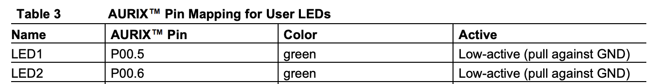
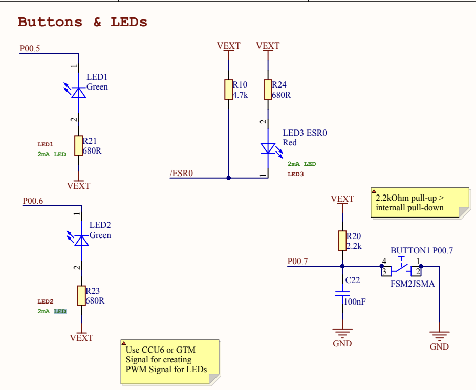
- AppLedType 인 전역변수 g_led를 생성하고 그 안에 LED1, LED2를 각각 설정한다.
- LED1: P00.5, output, paddriver-cmos
- LED2: P00.6, output, paddriver-cmos
- 해당 핀들은 TC275 Lite Kit의 LED에 연결된 포트이다.
- 다음 함수들을 사용해서 LED를 초기화한다.
- IfxPort_setPinHigh 를 통해서 핀상태를 HIGH로 만든다.
- TC275 LK의 LED의 기본 설정은 Active Low이므로 핀 상태를 HIGH만들어서 OFF 상태를 유지한다.
- IfxPort_setPinModeOutput 를 통해서 핀 모드를 설정한다.
- output mode: LED와 연결되므로 GPIO는 Output으로 되어야함
- push-pull mode: 내부 회로를 통해 출력을 결정함. 전원(VEXT)은 3.3V을 사용함
- IfxPort_setPinPadDriver 를통해서 핀의 pad driver를 설정한다.
LED in EVB usermanual(Click)
2.2.1.4. Transmit CAN Message
Source Code(Click)
/* Function to initialize both TX and RX messages with the default data values.
 * After initialization of the messages, the TX message will be transmitted.
 */
void transmitCanMessage(void)
{
    /* Define the content of the data to be transmitted */
    const uint32 dataLow  = 0xC0CAC01A;
    const uint32 dataHigh = 0xBA5EBA11;

    /* Invalidation of the RX message */
    IfxMultican_Message_init(&g_multican.rxMsg,
                             INVALID_ID_VALUE,
                             INVALID_DATA_VALUE,
                             INVALID_DATA_VALUE,
                             g_multican.canMsgObjConfig.control.messageLen);

    /* Initialization of the TX message */
    IfxMultican_Message_init(&g_multican.txMsg,
                             g_multican.canMsgObjConfig.messageId,
                             dataLow,
                             dataHigh,
                             g_multican.canMsgObjConfig.control.messageLen);

    /* Send the CAN message with the previously defined TX message content */
    while( IfxMultican_Status_notSentBusy ==
           IfxMultican_Can_MsgObj_sendMessage(&g_multican.canSrcMsgObj, &g_multican.txMsg) )
    {
    }
}
실제로 CAN 노드를 통해서 데이터를 보내는 함수이다.
- RX는 메세지를 받아야하므로 보낼 메세지가 아닌 값으로 초기화한다.
- id:
0xFFFFFFFF - data:
0xDEADBEEF
- id:
- TX는 보낼 메세지로 초기화 한다.
- messageId:
0x777 - dataLow:
0xC0CAC01A(cocacola) - dataHigh:
0xBA5EBA11(baseball)
- messageId:
- 아래 함수를 통해서 CAN 메세지를 보낸다
IfxMultican_Can_MsgObj_sendMessage(&g_multican.canSrcMsgObj, &g_multican.txMsg)- msg object를 확인해서 보낼 메세지가 있으면 메세지를 보낸다.
- 메세지를 보낼때까지(CAN BUS가 IDLE이 아니면) 송신을 계속 시도한다.
2.2.1.5. Interrupt Service Routines for TX
Source Code(Click)
IFX_INTERRUPT(canIsrTxHandler, 0, ISR_PRIORITY_CAN_TX);

void canIsrTxHandler(void)
{
    /* Just to indicate that the CAN message has been transmitted by turning on LED1 */
    IfxPort_setPinLow(g_led.led1.port, g_led.led1.pinIndex);
}
송신부의 Interrupt handler이다.
- 데이터가 송신될때 인터럽트 루틴이 발생해서 해당 함수가 불린다.
- 인터럽트 서비스 루틴을 등록하기 위해선 다음 매크로를 사용한다.
IFX_INTERRUPT(isr, vectabNum, priority)- 해당 매크로는
- isr: 인터럽트가 생기면 불리는 콜백함수
- vectabNum: Vector table number
- priority: 우선순위
- 인터럽트가 여러번 불릴 때 처리순서를 위한 우선순위
- 같은 순위로 만들수 없으므로 조금더 중요한 걸 높이 올림
- tx, rx의 우선순위는 tx를 높게 해놨음.
- 해당 핸들러가 불리면 GPIO 핀을 LOW로 내려서 LED1을 킴(active low)
2.2.1.6. Interrupt Service Routines for RX
Source Code(Click)
IFX_INTERRUPT(canIsrRxHandler, 0, ISR_PRIORITY_CAN_RX);

void canIsrRxHandler(void)
{
    IfxMultican_Status readStatus;

    /* Read the received CAN message and store the status of the operation */
    readStatus = IfxMultican_Can_MsgObj_readMessage(&g_multican.canDstMsgObj, &g_multican.rxMsg);

    /* If no new data has been received, report an error */
    if( !( readStatus & IfxMultican_Status_newData ) )
    {
        while(1)
        {
        }
    }

    /* If new data has been received but with one message lost, report an error */
    if( readStatus == IfxMultican_Status_newDataButOneLost )
    {
        while(1)
        {
        }
    }

    /* Finally, check if the received data matches with the transmitted one */
    if( ( g_multican.rxMsg.data[0] == g_multican.txMsg.data[0] ) &&
        ( g_multican.rxMsg.data[1] == g_multican.txMsg.data[1] ) &&
        ( g_multican.rxMsg.id == g_multican.txMsg.id ) )
    {
        /* Turn on the LED2 to indicate correctness of the received message */
        IfxPort_setPinLow(g_led.led2.port, g_led.led2.pinIndex);
    }
}
수신부의 Interrupt handler이다.
- 메세지가 수신되면 해당 핸들러가 불리고 다음을 수행함
- 수신된 메세지를 읽고 state를 저장함.
- 해당 데이터가 새로운 데이터인지 메세지가 손실되었는지 확인함.
- 정상 데이터라면 보낸 메세지와 받은 메세지가 같은지 확인하고 id도 같은지 확인함
- 다 같은 경우에만 GPIO 핀을 LOW로 내려서 LED2을 킴(active low)
- 실제로도 cocacola, baseball이 나오는지 확인 (결과 사진 필요)
2.2.2. MULTICAN in Flexible Data-Rate
MULTICAN_FD_1_KIT_TC275_LK-TR (Link)
- TC275 Lite Kit에 CAN Node를 CANFD 모드로 두 개 만들고, 루프백 모드를 사용해서 서로 통신한다.
- 예제 동작
- Node 0 sends data to Node 1
- if the transmission and reception are successful, an interrupt is generated.
- In the interrupt service routine, read the reception data and compare tx, rx data.
- If not errors detected, turn on LED
예제 “2.2.1.MULTICAN”과 겹치는 코드(비슷한 코드)는 스킵
2.2.2.1. core0_main
Source Code(Click)
uint8 g_currentCanFdUseCase = 0;
IfxCpu_syncEvent g_cpuSyncEvent = 0;

int core0_main(void)
{
    /* skip, similar code  */

    /* Application code: initialization of MULTICAN, LED, transmission and verification of the CAN messages */
    initMultican();
    initLed();

    for(g_currentCanFdUseCase = 0; g_currentCanFdUseCase < NUMBER_OF_CAN_FD_CASES; g_currentCanFdUseCase++)
    {
        transmitCanMessage();
        verifyCanMessage();

        if(g_status != CanCommunicationStatus_Success)
        {
            break;
        }
    }

    /* If there was no error, turn on the LED to indicate correctness of the received messages */
    if(g_status == CanCommunicationStatus_Success)
    {
        IfxPort_setPinLow(g_led1.port, g_led1.pinIndex);
    }

    /* skip, similar code */
}
- 전역 인터럽트 활성화
- WDG 비활성화
- Core 동기화
- CAN 예제 구동시 필요한 코드
- CAN 모듈 초기화: CAN FD 설정
- LED 모듈 초기화: LED1(pin00.5) 설정
- 메세지 전송 및 검증(4회 반복)
- 모든 메세지가 제대로 전송 된 경우 LED ON
- (꺼지지 않도록) 무한 루프
2.2.2.2. Initialize MultiCAN Module
Source Code(Click)
#define STANDARD_MESSAGE_ID_1 0x444     /* Message ID that is used in arbitration phase */
#define STANDARD_MESSAGE_ID_2 0x777     /* Message ID that is used in arbitration phase */
#define EXTENDED_MESSAGE_ID_1 0x1234567 /* Message ID that is used in arbitration phase */
#define EXTENDED_MESSAGE_ID_2 0xAABBCCD /* Message ID that is used in arbitration phase */

const canMessageObjectConfigType    g_messageObjectConf[NUMBER_OF_CAN_FD_CASES] =
   {
      /* message ID / Extended Frame / message Length / Fast bitrate */
      { STANDARD_MESSAGE_ID_1, FALSE, IfxMultican_DataLengthCode_8,  FALSE },
      { EXTENDED_MESSAGE_ID_1, TRUE,  IfxMultican_DataLengthCode_8,  TRUE  },
      { STANDARD_MESSAGE_ID_2, FALSE, IfxMultican_DataLengthCode_32, FALSE },
      { EXTENDED_MESSAGE_ID_2, TRUE,  IfxMultican_DataLengthCode_64, TRUE  }
   };

void initMultican(void)
{
    uint8 currentCanMessageObject;
    /* ==========================================================================================
     * CAN module configuration and initialization:
     * ==========================================================================================
     */
    IfxMultican_Can_initModuleConfig(&g_multican.canConfig, &MODULE_CAN);

    g_multican.canConfig.nodePointer[RX_INTERRUPT_SRC_ID].priority = ISR_PRIORITY_CAN_RX;

    IfxMultican_Can_initModule(&g_multican.can, &g_multican.canConfig);

    /* ==========================================================================================
     * Common CAN node configuration and initialization:
     * ==========================================================================================
     */
    IfxMultican_Can_Node_initConfig(&g_multican.canNodeConfig, &g_multican.can);

    g_multican.canNodeConfig.loopBackMode = TRUE;
    g_multican.canNodeConfig.flexibleDataRate = TRUE;

    g_multican.canNodeConfig.fdConfig.nominalBaudrate = 500000;
    g_multican.canNodeConfig.fdConfig.nominalSamplePoint = 8000;
    g_multican.canNodeConfig.fdConfig.nominalSynchJumpWidth = 2000;
    g_multican.canNodeConfig.fdConfig.fastBaudrate = 2000000;
    g_multican.canNodeConfig.fdConfig.fastSamplePoint = 7000;
    g_multican.canNodeConfig.fdConfig.fastSynchJumpWidth = 2000;
    g_multican.canNodeConfig.fdConfig.loopDelayOffset = 0;

    /* ==========================================================================================
     * CAN node 0 configuration and initialization:
     * =========================================================================================
     */
    g_multican.canNodeConfig.nodeId = IfxMultican_NodeId_0;

    IfxMultican_Can_Node_init(&g_multican.canNode0, &g_multican.canNodeConfig);

    /* ==========================================================================================
     * CAN node 1 configuration and initialization:
     * ==========================================================================================
     */
    g_multican.canNodeConfig.nodeId = IfxMultican_NodeId_1;

    IfxMultican_Can_Node_init(&g_multican.canNode1, &g_multican.canNodeConfig);

    /* ==========================================================================================
     * Source standard message objects configuration and initialization:
     * ==========================================================================================
     * These CAN message objects are assigned to CAN Node 0
     * ==========================================================================================
     */
    IfxMultican_Can_MsgObj_initConfig(&g_multican.canMsgObjConfig, &g_multican.canNode0);

    g_multican.canMsgObjConfig.frame = IfxMultican_Frame_transmit;
    g_multican.canMsgObjConfig.control.matchingId = TRUE;

    for(currentCanMessageObject = 0; currentCanMessageObject < NUMBER_OF_CAN_FD_CASES; currentCanMessageObject++)
    {
        g_multican.canMsgObjConfig.msgObjId = (IfxMultican_MsgObjId)currentCanMessageObject;
        g_multican.canMsgObjConfig.messageId = g_messageObjectConf[currentCanMessageObject].messageId;
        g_multican.canMsgObjConfig.control.extendedFrame = g_messageObjectConf[currentCanMessageObject].extendedFrame;
        g_multican.canMsgObjConfig.control.topMsgObjId = (2 * currentCanMessageObject) + SRC_EXTENDED_MO_OFFSET;
        g_multican.canMsgObjConfig.control.bottomMsgObjId = g_multican.canMsgObjConfig.control.topMsgObjId + 1;

        g_multican.canMsgObjConfig.control.messageLen = g_messageObjectConf[currentCanMessageObject].messageLen;
        g_multican.canMsgObjConfig.control.fastBitRate = g_messageObjectConf[currentCanMessageObject].fastBitRate;

        IfxMultican_Can_MsgObj_init(&g_multican.canSrcMsgObj[currentCanMessageObject], &g_multican.canMsgObjConfig);
    }

    /* ===========================================================================================
     * Destination standard message objects configuration and initialization:
     * ===========================================================================================
     * These CAN message objects are assigned to CAN Node 1
     * ===========================================================================================
     */
    IfxMultican_Can_MsgObj_initConfig(&g_multican.canMsgObjConfig, &g_multican.canNode1);

    g_multican.canMsgObjConfig.frame = IfxMultican_Frame_receive;
    g_multican.canMsgObjConfig.control.matchingId = TRUE;
    g_multican.canMsgObjConfig.rxInterrupt.enabled = TRUE;
    g_multican.canMsgObjConfig.rxInterrupt.srcId = RX_INTERRUPT_SRC_ID;

    for(currentCanMessageObject = 0; currentCanMessageObject < NUMBER_OF_CAN_FD_CASES; currentCanMessageObject++)
    {
        g_multican.canMsgObjConfig.msgObjId = (IfxMultican_MsgObjId)(currentCanMessageObject + DST_MO_OFFSET);
        g_multican.canMsgObjConfig.messageId = g_messageObjectConf[currentCanMessageObject].messageId;
        g_multican.canMsgObjConfig.control.extendedFrame = g_messageObjectConf[currentCanMessageObject].extendedFrame;
        g_multican.canMsgObjConfig.control.topMsgObjId = (2 * currentCanMessageObject) + DST_EXTENDED_MO_OFFSET;
        g_multican.canMsgObjConfig.control.bottomMsgObjId = g_multican.canMsgObjConfig.control.topMsgObjId + 1;

        g_multican.canMsgObjConfig.control.messageLen = g_messageObjectConf[currentCanMessageObject].messageLen;

        IfxMultican_Can_MsgObj_init(&g_multican.canDstMsgObj[currentCanMessageObject], &g_multican.canMsgObjConfig);
    }
}
- CAN Node RX 인터럽트 우선 순위 설정
- Rx 인터럽트만 사용함.
- CAN node 설정(Node0, Node1)
- loop back 모드 설정
- Flexible Data rate 모드 설정
- CAN FD 관련 설정
- nominal: 500kbps, 80% sample point, 20% sync jump width
- fast: 2000kbps, 70% sample point, 20% sync jump width
- loop delay offset: 0
- CAN Message Object 설정
- 일치하는 IDE 만 데이터 프레임을 허가함(
control.matchingId = TRUE;) - CAN Node 0(Tx)의 Message Object 설정 (메세지 4개)
- Message Object ID
- Message ID
- standard/extanded frame
- Top, Bottom Message Object Id
- Message Length
- fast Bit Rate
- CAN Node 1(Rx)의 Message Object 설정 (메세지 4개)
- 인터럽트 활성화 및 인터럽트 노드 포인터 정의
rxInterrupt.enabled = TRUE;rxInterrupt.srcId = RX_INTERRUPT_SRC_ID;
- Message Object ID
- Message ID
- standard/extanded frame
- Top, Bottom Message Object Id
- Message Length
- 인터럽트 활성화 및 인터럽트 노드 포인터 정의
- 일치하는 IDE 만 데이터 프레임을 허가함(
2.2.2.3. Transmit CAN Message
Source Code(Click)
void transmitCanMessage(void)
{
    uint8 currentDataPayloadByte;

    /* Invalidation of the RX message */
    IfxMultican_Message_longFrameInit(
        &g_multican.rxMsg,
        INVALID_ID_VALUE,
        INVALID_LENGTH_VALUE,
        INVALID_FAST_BITRATE_VALUE);

    /* Invalidation of the RX message data content */
    memset((void *)(&g_multican.rxData[0]), INVALID_RX_DATA_VALUE, MAXIMUM_CAN_FD_DATA_PAYLOAD);

    /* Invalidation of the TX message data content */
    memset((void *)(&g_multican.txData[0]), INVALID_TX_DATA_VALUE, MAXIMUM_CAN_FD_DATA_PAYLOAD);

    /* Initialization of the TX message data content */
    for(currentDataPayloadByte = 0;
        currentDataPayloadByte < g_dlcLookUpTable[g_messageObjectConf[g_currentCanFdUseCase].messageLen];
        currentDataPayloadByte++)
    {
        /* Each CAN message data payload byte is initialized in the following format:
         *
         * |          7 6          |       5 4 3 2 1 0      |
         * | g_currentCanFdUseCase | currentDataPayloadByte |
         * |       ( 0 - 3 )       |       ( 0 - 63 )       |
         */
        g_multican.txData[currentDataPayloadByte] =
            (g_currentCanFdUseCase << TX_DATA_INIT_SHIFT_OFFSET) |
            currentDataPayloadByte;
    }

    if(g_messageObjectConf[g_currentCanFdUseCase].messageLen > IfxMultican_DataLengthCode_8)
    {
        /* Initialization of the TX message (long frame) */
        IfxMultican_Message_longFrameInit(
            &g_multican.txMsg,
            g_messageObjectConf[g_currentCanFdUseCase].messageId,
            g_messageObjectConf[g_currentCanFdUseCase].messageLen,
            g_messageObjectConf[g_currentCanFdUseCase].fastBitRate);

        /* Send the CAN message with the previously defined TX message content */
        while(IfxMultican_Status_notSentBusy ==
            IfxMultican_Can_MsgObj_sendLongFrame(
               &g_multican.canSrcMsgObj[g_currentCanFdUseCase],
               &g_multican.txMsg,
               (uint32*)&g_multican.txData));
        {
        }
    }
    else
    {
        /* Initialization of the TX message (standard frame) */
        IfxMultican_Message_init(
            &g_multican.txMsg,
            g_messageObjectConf[g_currentCanFdUseCase].messageId,
            *(uint32*)&g_multican.txData[0],
            *(uint32*)&g_multican.txData[4],
            g_messageObjectConf[g_currentCanFdUseCase].messageLen);

        /* Send the CAN message with the previously defined TX message content */
        while(IfxMultican_Status_notSentBusy ==
            IfxMultican_Can_MsgObj_sendMessage(
                &g_multican.canSrcMsgObj[g_currentCanFdUseCase],
                &g_multican.txMsg));
        {
        }
    }

    /* Wait until previously transmitted data has been received in the destination message object */
    while(g_isrRxCount == g_currentCanFdUseCase)
    {
    }
}
- 메세지 당 한번씩 호출
g_messageObjectConf{ STANDARD_MESSAGE_ID_1, FALSE, IfxMultican_DataLengthCode_8, FALSE }{ EXTENDED_MESSAGE_ID_1, TRUE, IfxMultican_DataLengthCode_8, TRUE }{ STANDARD_MESSAGE_ID_2, FALSE, IfxMultican_DataLengthCode_32, FALSE }{ EXTENDED_MESSAGE_ID_2, TRUE, IfxMultican_DataLengthCode_64, TRUE }
- CAN Message 초기화
- Rx message data: invalid data
- Tx message data: long frame data
- message data content의 모든 바이트를 하나하나 설정
- CAN BUS가 Not busy 일때 메세지 송신
- DLC8 초과면 Extended Frame으로 송신(
IfxMultican_Can_MsgObj_sendLongFrame) - DLC8 이하면 Standard frame으로 송신(
IfxMultican_Can_MsgObj_sendMessage)
- DLC8 초과면 Extended Frame으로 송신(
- 메세지가 수신될까지(Rx ISR이 불릴때까지) 대기
2.2.2.4. Interrupt Service Routines for RX
Source Code(Click)
IFX_INTERRUPT(canIsrRxHandler, 0, ISR_PRIORITY_CAN_RX);

void canIsrRxHandler(void)
{
    IfxMultican_Status readStatus;

    if(g_messageObjectConf[g_isrRxCount].messageLen > IfxMultican_DataLengthCode_8)
    {
        /* Read the received long frame CAN message and store the status of the operation */
        readStatus = IfxMultican_MsgObj_readLongFrame(
            g_multican.canDstMsgObj[g_isrRxCount].node->mcan,
            g_multican.canDstMsgObj[g_isrRxCount].msgObjId,
            &g_multican.rxMsg,
            (uint32*)&g_multican.rxData);
    }
    else
    {
        /* Read the received standard frame CAN message and store the status of the operation */
        readStatus = IfxMultican_Can_MsgObj_readMessage(
            &g_multican.canDstMsgObj[g_isrRxCount],
            &g_multican.rxMsg);

        memcpy((void *)(
            &g_multican.rxData[0]),
            (void *)(&g_multican.rxMsg.data[0]),
            IfxMultican_DataLengthCode_8);
    }

    /* If no new data has been received, report an error */
    if(!( readStatus & IfxMultican_Status_newData ))
    {
        g_status = CanCommunicationStatus_Error_noNewDataReceived;
    }

    /* If new data has been received but with one message lost, report an error */
    if(readStatus == IfxMultican_Status_newDataButOneLost)
    {
        g_status = CanCommunicationStatus_Error_newDataButOneLost;
    }

    /* If there was no error, increment the counter to indicate the number of successfully received CAN messages */
    if (g_status == CanCommunicationStatus_Success)
    {
        g_isrRxCount++;
    }
}
IFX_INTERRUPT로 우선순위 및 ISR 콜백함수 설정- 수신된 메세지를 읽고 오류가 없는지 확인함
- Extended frame(
IfxMultican_MsgObj_readLongFrame) - Standard frame(
IfxMultican_Can_MsgObj_readMessage) - 오류는 새로운 데이터가 없는 경우, 새로운 데이터는 있으나 손실된 경우가 있다.
- Extended frame(
- 에러가 없으면 카운터(
g_isrRxCount)를 증가시킴
IfxMultican.c 와 IfxMultican_Can.c의 함수(API) 차이점 (Click)
| in IfxMultican.c | in IfxMultican_Can.c | |
|---|---|---|
| Standard | 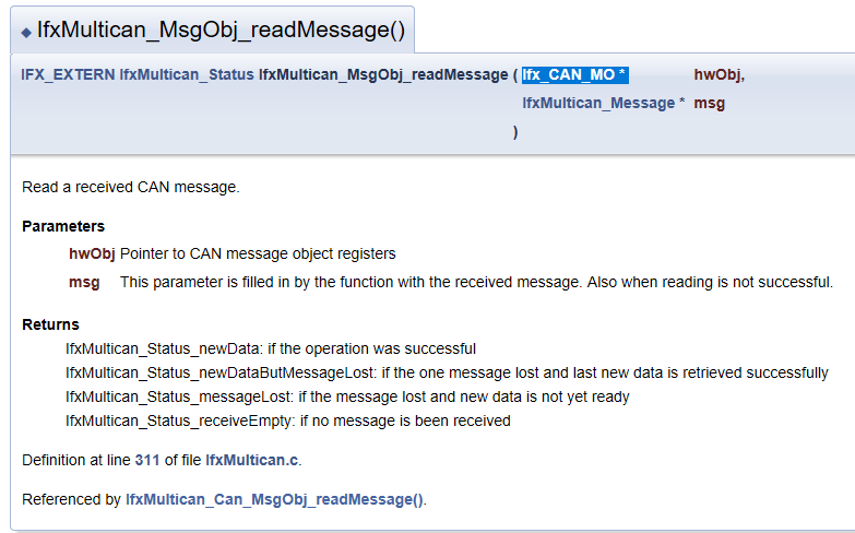 |
 |
| Extended | 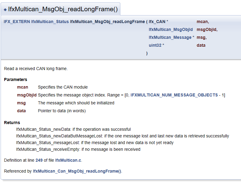 |
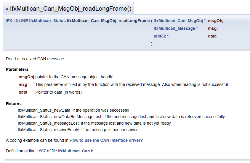 |
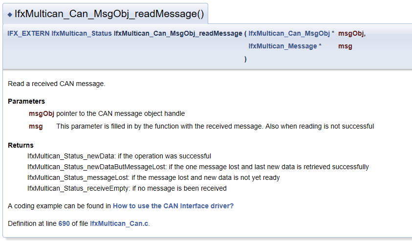
IfxMultican_Status IfxMultican_Can_MsgObj_readMessage
(
   IfxMultican_Can_MsgObj *msgObj,
   IfxMultican_Message *msg
)
{
    IfxMultican_Status   status = IfxMultican_Status_ok;
    IfxMultican_MsgObjId objId;

    if (msgObj->msgObjCount > 1)
    {
        /* for FIFO message Objects */
        objId = msgObj->fifoPointer;
    }
    else
    {
        /* for standard message Objects */
        objId = msgObj->msgObjId;
    }

    Ifx_CAN_MO *hwObj = IfxMultican_MsgObj_getPointer(msgObj->node->mcan, objId);

    /* clear pending flag */
    IfxMultican_MsgObj_clearRxPending(hwObj);

    /* read the message object */
    status = IfxMultican_MsgObj_readMessage(hwObj, msg);

    /* if successfull: */
    if (status & IfxMultican_Status_newData)
    {
        if (msgObj->msgObjCount > 1)
        {
            /* set next message object(MOSTAT.PNEXT) of the current object as the next txFIFO slave object */
            msgObj->fifoPointer = IfxMultican_MsgObj_getBottomObjectPointer(hwObj);
        }
        else
        {}
    }

    return status;
}
- 내부 코드를 보면 다음과 같다.
- 코드를 분석하면 Message Object 에 대해서 ID를 구하고 message object 데이터를 읽는걸 볼수 있다. 즉,
IfxMultican_Can에 있는 함수들은IfxMultican의 함수를 사용해서 메세지를 읽는다. 어떤 함수를 사용하든 데이터를 읽을수 있다. - 추가적으로,
IfxMultican_Can_MsgObj_readLongFrame은 iLLD User manaul엔 등록되어있는데 실제 예제코드엔 들어있지 않다. 그러므로IfxMultican_MsgObj_readLongFrame만 사용할수 있다.
2.2.2.5. Verify Can Message
Source Code(Click)
void verifyCanMessage(void)
{
    uint8 currentDataPayloadByte;

    /* Check if the received message ID does NOT match with the expected message ID.
     * If this is the case, an error should be reported.
     */
    if(g_multican.rxMsg.id != g_multican.txMsg.id)
    {
        g_status = CanCommunicationStatus_Error_notExpectedMessageId;
    }

    /* Check if the received message length does NOT match with the expected message length.
     * If this is the case, an error should be reported.
     */
    if(g_multican.rxMsg.lengthCode != g_multican.txMsg.lengthCode)
    {
        g_status = CanCommunicationStatus_Error_notExpectedLengthCode;
    }

    /* Check if the received fast bit rate bit does NOT match with the expected fast bit rate value.
     * If this is the case, an error should be reported.
     */
    if(g_multican.rxMsg.fastBitRate != g_multican.txMsg.fastBitRate)
    {
        g_status = CanCommunicationStatus_Error_notExpectedFastBitrateValue;
    }

    /* Finally, check if the received data does NOT match with the transmitted one.
     * If this is the case, an error should be reported.
     *
     * Both "rxData" and "txData" arrays have the size of MAXIMUM_CAN_FD_DATA_PAYLOAD (64 bytes). Additionally, both of
     * the arrays are fully initialized so the possible incorrect number of transmitted bytes can be detected.
     * For this reason, the check is performed in two steps:
     *     - First "for" loop compares the valid expected data to the received data. The "currentDataPayloadByte"
     *       iterator variable is incremented to the number of bytes defined by the "g_multican.rxMsg.lengthCode"
     *       variable and can be either 8, 32, or 64 bytes. This value equals to the number of valid expected data bytes.
     *     - Second "for" loop checks the invalid data to make sure that the content has not been changed.
     *       The "currentDataPayloadByte" iterator variable is incremented from the current value of the variable
     *       (for this reason, the initialization part of the second "for" loop is omitted) to the
     *       MAXIMUM_CAN_FD_DATA_PAYLOAD (64 bytes) value.
     */
    for(currentDataPayloadByte = 0;
        currentDataPayloadByte < g_dlcLookUpTable[g_multican.rxMsg.lengthCode];
        currentDataPayloadByte++)
    {
        if(g_multican.rxData[currentDataPayloadByte] != g_multican.txData[currentDataPayloadByte])
        {
            g_status = CanCommunicationStatus_Error_notExpectedData;
        }
    }

    for(/*...*/;
        currentDataPayloadByte < MAXIMUM_CAN_FD_DATA_PAYLOAD;
        currentDataPayloadByte++)
    {
        if(g_multican.rxData[currentDataPayloadByte] != INVALID_RX_DATA_VALUE)
        {
            g_status = CanCommunicationStatus_Error_notExpectedData;
        }
    }
}
- 실제 수신된 데이터가 송신한 데이터랑 같은지 검증함.
- Message ID
- Message Length
- Fast bit rate bit value
- Data
- 검증에 실패하면 각 단계별로 에러코드를 담아서 보냄
- early return을 사용안해서 앞에서 검증 실패해도 뒷부분까지 다 검증하는듯하다.
2.2.3. MULTICAN using a Gateway with a TX FIFO
MULTICAN_GW_TX_FIFO_1_KIT_TC275_LK-TR (Link)
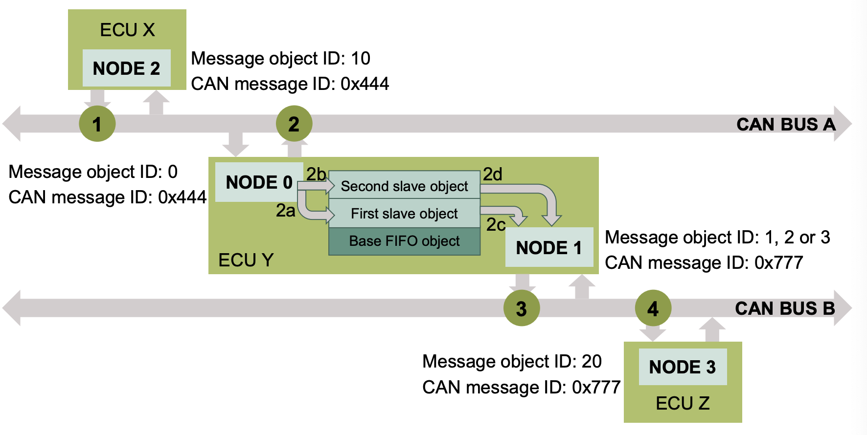
- TX FIFO 구조를 갖는 노드를 만들고, 게이트웨이(Gateway)를 사용해서 CAN BUS 간 데이터를 교환한다.
- 예제 동작
- Node 2에서 CAN BUS(A)로 메세지를 보낸다.(루프백모드일때 모든 노드가 CAN BUS에 접근할수 있음)
- Node 0이 전송된 메세지를 수신하면 게이트웨이를 통해 Node 1로 전송한다.
- Node 1에 TX FIFO buffer Structure 정의함
- Node 1은 게이트웨이를 통해 메세지가 수신되면 Node 3에 전송한다. (CAN BUS B)
- Node 3에서 데이터를 받으면 (Node 2에서) 전송한 메세지와 비교하고, 값이 같으면 LED를 킨다.
- 필요 지식
- Gateway mode: CPU 개입없이 두개의 독립적인 CAN 버스 간 데이터 전송하는 것.
- 이번 예제에선 CAN BUS A의 데이터를 CAN BUS B로 전송함.
- FIFO Buffer structure: 여러 메세지를 수신했을때 들어온 순서대로 처리하는 것.
- CPU load가 높은 경우 메세지 처리 시간이 충분하지 않아 모든 메세지를 처리하기 어려울수 있음. 이럴때 FIFO 구조를 사용해서 모든 메세지를 처리할수 있도록 함.
- Gateway mode: CPU 개입없이 두개의 독립적인 CAN 버스 간 데이터 전송하는 것.
선행 예제들과 겹치는 코드(비슷한 코드)는 스킵
2.2.3.1. core0_main
- 전역 인터럽트 활성화
- WDG 비활성화
- Core 동기화
- CAN 예제 구동시 필요한 코드
- CAN 모듈 초기화: CAN Tx Gateway 설정
- LED 모듈 초기화: LED1(pin00.5) 설정
- 메세지 전송
- 메세지 검증
- 메세지가 제대로 전송 된 경우 LED ON
- (꺼지지 않도록) 무한 루프
2.2.3.2. Initialize MultiCAN Module
Source Code(Click)
void initMultican(void)
{
    uint8 currentCanNode;

    /* ==========================================================================================
     * CAN module configuration and initialization:
     * ==========================================================================================
     */
    IfxMultican_Can_initModuleConfig(&g_multican.canConfig, &MODULE_CAN);

    g_multican.canConfig.nodePointer[RX_INTERRUPT_SRC_ID].priority = ISR_PRIORITY_CAN_RX;

    IfxMultican_Can_initModule(&g_multican.can, &g_multican.canConfig);

    /* ==========================================================================================
     * Common CAN node configuration and initialization:
     * ==========================================================================================
     */
    IfxMultican_Can_Node_initConfig(&g_multican.canNodeConfig, &g_multican.can);

    g_multican.canNodeConfig.loopBackMode = TRUE;

    for(currentCanNode = 0; currentCanNode < NUMBER_OF_CAN_NODES; currentCanNode++)
    {
        g_multican.canNodeConfig.nodeId = (IfxMultican_NodeId)currentCanNode;

        IfxMultican_Can_Node_init(&g_multican.canNode[currentCanNode], &g_multican.canNodeConfig);
    }

    /* ======================================================================
     * Gateway source message object configuration and initialization:
     * This CAN message object is assigned to CAN Node 0
     * ======================================================================
     */
    IfxMultican_Can_MsgObj_initConfig(&g_multican.canMsgObjConfig, &g_multican.canNode[0]);

    g_multican.canMsgObjConfig.msgObjId = GTW_SRC_MESSAGE_OBJECT_ID;
    g_multican.canMsgObjConfig.messageId = GTW_SRC_MESSAGE_ID;
    g_multican.canMsgObjConfig.msgObjCount = TX_FIFO_SIZE;
    g_multican.canMsgObjConfig.frame = IfxMultican_Frame_receive;
    g_multican.canMsgObjConfig.firstSlaveObjId = SLAVE_MESSAGE_OBJECT_ID;

    g_multican.canMsgObjConfig.gatewayTransfers = TRUE;
    g_multican.canMsgObjConfig.gatewayConfig.copyDataLengthCode = TRUE;
    g_multican.canMsgObjConfig.gatewayConfig.copyData = TRUE;
    g_multican.canMsgObjConfig.gatewayConfig.copyId = FALSE;
    g_multican.canMsgObjConfig.gatewayConfig.enableTransmit = TRUE;
    g_multican.canMsgObjConfig.gatewayConfig.gatewayDstObjId = SLAVE_MESSAGE_OBJECT_ID;

    IfxMultican_Can_MsgObj_init(&g_multican.canGtwSrcMsgObj, &g_multican.canMsgObjConfig);

    /* =====================================================================================
     * Gateway destination (implemented as TX FIFO object) configuration and initialization:
     * This CAN message object is assigned to CAN Node 1
     * =====================================================================================
     */
    IfxMultican_Can_MsgObj_initConfig(&g_multican.canMsgObjConfig, &g_multican.canNode[1]);

    g_multican.canMsgObjConfig.msgObjId = GTW_DST_MESSAGE_OBJECT_ID;
    g_multican.canMsgObjConfig.messageId = GTW_DST_MESSAGE_ID;
    g_multican.canMsgObjConfig.msgObjCount = TX_FIFO_SIZE;
    g_multican.canMsgObjConfig.frame = IfxMultican_Frame_transmit;
    g_multican.canMsgObjConfig.firstSlaveObjId = SLAVE_MESSAGE_OBJECT_ID;

    IfxMultican_Can_MsgObj_init(&g_multican.canGtwDstMsgObj, &g_multican.canMsgObjConfig);

    /* ==========================================================================
     * This CAN message object is assigned to CAN Node 2
     * ==========================================================================
     */
    IfxMultican_Can_MsgObj_initConfig(&g_multican.canMsgObjConfig, &g_multican.canNode[2]);

    g_multican.canMsgObjConfig.msgObjId = SRC_MESSAGE_OBJECT_ID;
    g_multican.canMsgObjConfig.messageId = SRC_MESSAGE_ID;
    g_multican.canMsgObjConfig.frame = IfxMultican_Frame_transmit;

    IfxMultican_Can_MsgObj_init(&g_multican.canSrcMsgObj, &g_multican.canMsgObjConfig);

    /* ==========================================================================
     * Destination standard message object configuration and initialization:
     * This CAN message object is assigned to CAN Node 3
     * ==========================================================================
     */
    IfxMultican_Can_MsgObj_initConfig(&g_multican.canMsgObjConfig, &g_multican.canNode[3]);

    g_multican.canMsgObjConfig.msgObjId = DST_MESSAGE_OBJECT_ID;
    g_multican.canMsgObjConfig.messageId = DST_MESSAGE_ID;
    g_multican.canMsgObjConfig.frame = IfxMultican_Frame_receive;
    g_multican.canMsgObjConfig.rxInterrupt.enabled = TRUE;
    g_multican.canMsgObjConfig.rxInterrupt.srcId = RX_INTERRUPT_SRC_ID;

    IfxMultican_Can_MsgObj_init(&g_multican.canDstMsgObj, &g_multican.canMsgObjConfig);
}
- CAN Node RX 인터럽트 우선순위 설정
- CAN Node 공통 설정: 루프백 모드
- CAN Node 0의 Message Object 설정 및 gateway source 설정
- FIFO 개수 설정 (2개)
- RX Message object 설정(CAN BUS로 들어오는 데이터를 받기 위함)
- FIFO의 첫번째 slave object를 TX FIFO base object 다음 첫번째 메세지로 설정
- 게이트웨이 전송 활성화(게이트웨이 소스 개체 정의)
- 게이트웨이로 전송할 데이터 정의(id 빼고 복사해서 사용)
- CAN Node 1의 Message Object 설정 및 gateway destination 설정
- FIFO로 받는 MO 설정
- CAN Node 2 설정: Tx Message Object
- CAN Node 3 설정: Rx Message Object
2.2.3.3. Transmit CAN Message
Source Code(Click)
void transmitCanMessages(void)
{
    /* Invalidation of the RX messages */
    for(g_currentCanMessage = 0; g_currentCanMessage < NUMBER_OF_CAN_MESSAGES; g_currentCanMessage++)
    {
        IfxMultican_Message_init(&g_multican.rxMsg[g_currentCanMessage],
                                 INVALID_ID_VALUE,
                                 INVALID_DATA_VALUE,
                                 INVALID_DATA_VALUE,
                                 INVALID_LENGTH_VALUE);
    }

    for(g_currentCanMessage = 0; g_currentCanMessage < NUMBER_OF_CAN_MESSAGES; g_currentCanMessage++)
    {
        /* Initialization of the TX message */
        IfxMultican_Message_init(&g_multican.txMsg,
                                 SRC_MESSAGE_ID,
                                 ( g_canInitialMessageData[0] | g_currentCanMessage ),
                                 ( g_canInitialMessageData[1] | g_currentCanMessage ),
                                 g_multican.canMsgObjConfig.control.messageLen);

        /* Send the CAN message with the previously defined TX message content */
        while(IfxMultican_Status_notSentBusy ==
           IfxMultican_Can_MsgObj_sendMessage(&g_multican.canSrcMsgObj, &g_multican.txMsg))
        {
        }

        /* Wait until previously transmitted data has been received in the destination message object and no error has been detected. If the code execution stops at this point, check the "g_status" variable.
         */
        while(g_isrRxCount == g_currentCanMessage)
        {
        }
    }
}
- CAN Message 초기화
- Rx message data: invalid data
- Tx message data: long frame data
- message data content의 모든 바이트를 하나하나 설정
- CAN BUS가 Not busy 일때 메세지 송신
- DLC8 이하면 Standard frame으로 송신(
IfxMultican_Can_MsgObj_sendMessage)
- DLC8 이하면 Standard frame으로 송신(
- 메세지가 수신될까지(Rx ISR이 불릴때까지) 대기
2.2.3.4. Verify Can Message
Source Code(Click)
void verifyCanMessages(void)
{
    Ifx_CAN_MO *hwObj;

    /* Get the pointer to the gateway source object. */
    hwObj = IfxMultican_MsgObj_getPointer(g_multican.can.mcan, GTW_SRC_MESSAGE_OBJECT_ID);

    /* Check if the CUR value does not match with the expected data in the gateway source object.
     * If this is the case, an error should be reported.
     */
    if(EXPECTED_CUR_POINTER_VALUE != hwObj->FGPR.B.CUR)
    {
        g_status = CanCommunicationStatus_Error_notExpectedFifoCurPointer;
    }

    /* Get the pointer to the gateway destination (TX FIFO base) object */
    hwObj = IfxMultican_MsgObj_getPointer(g_multican.can.mcan, GTW_DST_MESSAGE_OBJECT_ID);

    /* Check if the CUR value does not match with the expected data in the gateway destination object.
     * If this is the case, an error should be reported.
     */
    if(EXPECTED_CUR_POINTER_VALUE != hwObj->FGPR.B.CUR)
    {
        g_status = CanCommunicationStatus_Error_notExpectedFifoCurPointer;
    }

    for(g_currentCanMessage = 0; g_currentCanMessage < NUMBER_OF_CAN_MESSAGES; g_currentCanMessage++)
    {
        /* Check if the received message ID matches with the transmitted message ID.
         * If this is the case, an error should be reported. Source standard message object and destination
         * standard message object have different message ID configuration.
         */
        if(g_multican.rxMsg[g_currentCanMessage].id == SRC_MESSAGE_ID)
        {
            g_status = CanCommunicationStatus_Error_notExpectedMessageId;
            break;
        }

        /* Check if the received message length does NOT match with the expected message length.
         * If this is the case, an error should be reported.
         */
        if(g_multican.rxMsg[g_currentCanMessage].lengthCode != g_multican.canMsgObjConfig.control.messageLen)
        {
            g_status = CanCommunicationStatus_Error_notExpectedLengthCode;
            break;
        }

        /* Finally, check if a received data does NOT match with the transmitted one
         * If this is the case, an error should be reported.
         */
        if((g_multican.rxMsg[g_currentCanMessage].data[0] != (g_canInitialMessageData[0] | g_currentCanMessage)) ||
            (g_multican.rxMsg[g_currentCanMessage].data[1] != (g_canInitialMessageData[1] | g_currentCanMessage)))
        {
            g_status = CanCommunicationStatus_Error_notExpectedData;
            break;
        }
    }

    /* If there was no error, turn on the LED1 to indicate correctness of the received messages */
    if(g_status == CanCommunicationStatus_Success)
    {
        IfxPort_setPinLow(g_led1.port, g_led1.pinIndex);
    }
}
- 메세지를 수신한뒤 아래 확인
- source, destination object 값 비교
- Tx, Rx Message ID 비교
- Data Length 및 실제 데이터 값 비교
- 다 일치하면 LED 점등. 하나라도 실패하면 에러 리턴(g_status)
2.2.4. MULTICAN using RX FIFO
MULTICAN_RX_FIFO_1_KIT_TC275_LK-TR (Link)
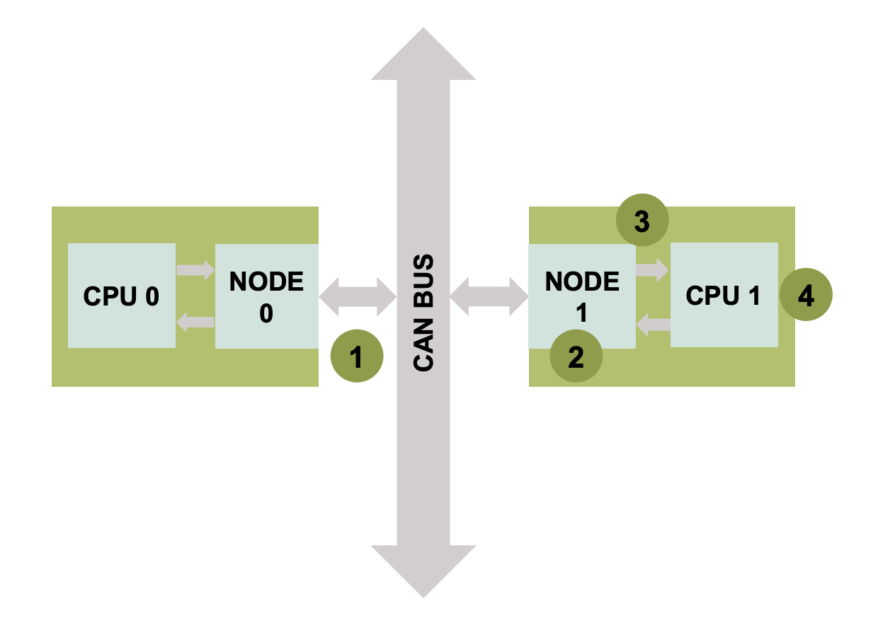
- RX FIFO 구조를 만들고 노드간 데이터를 교환한다.
- 예제 동작
- Node 0 에서 데이터를 보낸다.
- Node 1은 RX FIFO에 전송된 메세지를 저장한다.
- FIFO가 임계값에 도달하면 ISR이 발생하고, 이때 CPU1이 ISR을 처리한다.
- ISR이 처리될때 수신된 CAN 메세지를 모두 읽고 전송된 메세지와 비교한다. 값이 같으면 LED를 킨다.
- 필요 지식
- 멀티코어
- RX FIFO
2.2.4.1. core0_main
Source Code(Click)
IfxCpu_syncEvent g_cpuSyncEvent = 0;

int core0_main(void)
{
    IfxCpu_enableInterrupts();

    IfxScuWdt_disableCpuWatchdog(IfxScuWdt_getCpuWatchdogPassword());
    IfxScuWdt_disableSafetyWatchdog(IfxScuWdt_getSafetyWatchdogPassword());

    IfxCpu_emitEvent(&g_cpuSyncEvent);
    IfxCpu_waitEvent(&g_cpuSyncEvent, 1);

    initMultican();
    transmitCanMessages();

    while(1)
    {
    }
    return (1);
}
- 전역 인터럽트 활성화
- WDG 비활성화
- Core 동기화
- CAN 예제 구동시 필요한 코드
- CAN 모듈 초기화: CAN RX FIFO 설정
- 메세지 전송
- (꺼지지 않도록) 무한 루프
2.2.4.2. Initialize MultiCAN Module
Source Code(Click)
void initMultican(void)
{
    Ifx_CAN_MO *hwObj;

    /* ==========================================================================================
     * CAN module configuration and initialization:
     * ==========================================================================================
     */
    IfxMultican_Can_initModuleConfig(&g_multican.canConfig, &MODULE_CAN);

    g_multican.canConfig.nodePointer[OVERFLOW_INTERRUPT_SRC_ID].priority = ISR_PRIORITY_CAN_OVERFLOW;
    g_multican.canConfig.nodePointer[OVERFLOW_INTERRUPT_SRC_ID].typeOfService = ISR_PROVIDER_CAN_OVERFLOW;

    IfxMultican_Can_initModule(&g_multican.can, &g_multican.canConfig);

    /* ==========================================================================================
     * Common CAN node configuration and initialization:
     * ==========================================================================================
     */
    IfxMultican_Can_Node_initConfig(&g_multican.canNodeConfig, &g_multican.can);

    g_multican.canNodeConfig.loopBackMode = TRUE;

    /* ===================================================================
     * CAN node 0 configuration and initialization:
     * ===================================================================
     */
    g_multican.canNodeConfig.nodeId = IfxMultican_NodeId_0;

    IfxMultican_Can_Node_init(&g_multican.canNode0, &g_multican.canNodeConfig);

    /* ===================================================================
     * CAN node 1 configuration and initialization:
     * ===================================================================
    */
    g_multican.canNodeConfig.nodeId = IfxMultican_NodeId_1;

    IfxMultican_Can_Node_init(&g_multican.canNode1, &g_multican.canNodeConfig);

    /* ===================================================================
     * Source standard message object configuration and initialization:
     * This CAN message object is assigned to CAN Node 0
     * ===================================================================
     */
    IfxMultican_Can_MsgObj_initConfig(&g_multican.canMsgObjConfig, &g_multican.canNode0);

    g_multican.canMsgObjConfig.msgObjId = SRC_MESSAGE_OBJECT_ID;
    g_multican.canMsgObjConfig.messageId = CAN_MESSAGE_ID;
    g_multican.canMsgObjConfig.frame = IfxMultican_Frame_transmit;

    IfxMultican_Can_MsgObj_init(&g_multican.canSrcMsgObj, &g_multican.canMsgObjConfig);

    /* ===================================================================
     * RX FIFO structure configuration and initialization:
     * This CAN message object is assigned to CAN Node 1
     * ===================================================================
     */
    IfxMultican_Can_MsgObj_initConfig(&g_multican.canMsgObjConfig, &g_multican.canNode1);

    g_multican.canMsgObjConfig.msgObjId = RX_FIFO_BASE_OBJECT_ID;
    g_multican.canMsgObjConfig.messageId = CAN_MESSAGE_ID;
    g_multican.canMsgObjConfig.msgObjCount = RX_FIFO_SIZE;
    g_multican.canMsgObjConfig.frame = IfxMultican_Frame_receive;
    g_multican.canMsgObjConfig.firstSlaveObjId = SLAVE_MESSAGE_OBJECT_ID;

    IfxMultican_Can_MsgObj_init(&g_multican.canDstMsgObj, &g_multican.canMsgObjConfig);

    hwObj = IfxMultican_MsgObj_getPointer(g_multican.can.mcan, RX_FIFO_BASE_OBJECT_ID);
    IfxMultican_MsgObj_setOverflowInterrupt(hwObj, TRUE);
    IfxMultican_MsgObj_setTransmitInterruptNodePointer(hwObj, OVERFLOW_INTERRUPT_SRC_ID);
    IfxMultican_MsgObj_setSelectObjectPointer(hwObj, SLAVE_MESSAGE_OBJECT_ID);
}
- 인터럽트 우선순위 설정.
- overflow ISR
- 루프백 모드 설정
- Message Object 설정
- CAN Node 0: TX
- RX FIFO Base object와 같은 CAN Message ID 로 설정
- CAN Node 1: RX
- FIFO 크기 3
- Overflow 인터럽트 활성화
2.2.4.3. core1_main
Source Code(Click)
extern IfxCpu_syncEvent g_cpuSyncEvent;
boolean g_allMessagesReceived = FALSE;

int core1_main(void)
{
    IfxCpu_enableInterrupts();

    IfxScuWdt_disableCpuWatchdog(IfxScuWdt_getCpuWatchdogPassword());

    IfxCpu_emitEvent(&g_cpuSyncEvent);
    IfxCpu_waitEvent(&g_cpuSyncEvent, 1);

    initLed();

    while(!g_allMessagesReceived)
    {
    }
    verifyCanMessages();

    while(1)
    {
    }
    return (1);
}
- 전역 인터럽트 활성화
- WDG 비활성화
- Core 동기화
- CAN 예제 구동시 필요한 코드
- LED 모듈 초기화: LED1(pin00.5) 설정
- 메세지 갯수 확인
- 메세지 검증
- 메세지가 제대로 전송 된 경우 LED ON
- (꺼지지 않도록) 무한 루프
2.2.4.4. Interrupt Service Routines for RX
Source Code(Click)
IFX_INTERRUPT(canIsrOverflowHandler, 1, ISR_PRIORITY_CAN_OVERFLOW);

void canIsrOverflowHandler(void)
{
    IfxMultican_Status readStatus;
    uint8 currentCanMessage;
    static volatile uint8 numOfReceivedMessages = 0;

    for(currentCanMessage = 0; currentCanMessage < RX_FIFO_SIZE; currentCanMessage++)
    {
        /* Read the received CAN message and store the status of the operation */
        readStatus = IfxMultican_Can_MsgObj_readMessage(&g_multican.canDstMsgObj, &g_multican.rxMsg[numOfReceivedMessages]);

        /* If no new data has been received, report an error */
        if(readStatus != IfxMultican_Status_newData)
        {
            g_status = CanCommunicationStatus_Error_noNewDataReceived;
        }

        /* If a new data has been received but one message was lost, report an error */
        if(readStatus == IfxMultican_Status_newDataButOneLost)
        {
            g_status = CanCommunicationStatus_Error_newDataButOneLost;
        }

        /* If there was no error, increment the counter to indicate the number of successfully received CAN messages */
        if (g_status == CanCommunicationStatus_Success)
        {
            numOfReceivedMessages++;

            if(numOfReceivedMessages == NUMBER_OF_RECEIVED_MESSAGES)
            {
                g_allMessagesReceived = TRUE;
            }
        }
    }
}
- overflow 인터럽트가 발생되면 해당 함수 실행
- FIFO 크기만큼 반복 수행
- 메세지 읽고 작업상태 저장
- 수신한 데이터 없으면 에러 발생
- 데이터는 수신되었지만 잃어버렸으면 에러 발생
- 모든 메세지 받았을 때
g_allMessagesReceived를TRUE로 변경
2.2.4.5. Verify Can Message
Source Code(Click)
void verifyCanMessages(void)
{
    uint8 currentCanMessage;

    for(currentCanMessage = 0; currentCanMessage < NUMBER_OF_RECEIVED_MESSAGES; currentCanMessage++)
    {
        /* Check if the received message ID does NOT match with the transmitted message ID.
         * If this is the case, an error should be reported.
         */
        if(g_multican.rxMsg[currentCanMessage].id != CAN_MESSAGE_ID)
        {
            g_status = CanCommunicationStatus_Error_notExpectedMessageId;
            break;
        }

        /* Check if the received message length does NOT match with the expected message length.
         * If this is the case, an error should be reported.
         */
        if(g_multican.rxMsg[currentCanMessage].lengthCode != g_multican.canMsgObjConfig.control.messageLen)
        {
            g_status = CanCommunicationStatus_Error_notExpectedLengthCode;
            break;
        }

        /* Finally, check if the received data does NOT match with the transmitted one
         * If this is the case, an error should be reported.
         */
        if((g_multican.rxMsg[currentCanMessage].data[0] != (g_canInitialMessageData[0] | currentCanMessage)) ||
            (g_multican.rxMsg[currentCanMessage].data[1] != (g_canInitialMessageData[1] | currentCanMessage)))
        {
            g_status = CanCommunicationStatus_Error_notExpectedData;
            break;
        }
    }

    for(/*...*/; currentCanMessage < NUMBER_OF_CAN_MESSAGES; currentCanMessage++)
    {
        /* Check if the received message ID does NOT match invalid ID value.
         * If this is the case, an error should be reported.
         */
        if(g_multican.rxMsg[currentCanMessage].id != INVALID_ID_VALUE)
        {
            g_status = CanCommunicationStatus_Error_notExpectedMessageId;
            break;
        }

        /* Check if the received message length does NOT match invalid length value.
         * If this is the case, an error should be reported.
         */
        if(g_multican.rxMsg[currentCanMessage].lengthCode != INVALID_LENGTH_VALUE)
        {
            g_status = CanCommunicationStatus_Error_notExpectedLengthCode;
            break;
        }

        /* Finally, check if a received data does NOT match invalid data value.
         * If this is the case, an error should be reported.
         */
        if((g_multican.rxMsg[currentCanMessage].data[0] != INVALID_DATA_VALUE) ||
            (g_multican.rxMsg[currentCanMessage].data[1] != INVALID_DATA_VALUE))
        {
            g_status = CanCommunicationStatus_Error_notExpectedData;
            break;
        }
    }

    /* If there was no error, turn on the LED1 to indicate correctness of the received messages */
    if(g_status == CanCommunicationStatus_Success)
    {
        IfxPort_setPinLow(g_led1.port, g_led1.pinIndex);
    }
}
- 모든 메세지를 받은 이후에 실행되는 함수
- 메세지 ID 확인
- 메세지 길이 확인
- 데이터 확인
- for 반복문이 두번 있음
- 첫번째 반복문에선 실제 수신한 데이터와 예상한 데이터를 비교함
- 두번째 반복문에선 초기화 값이 변경되지 않았는지 확인함
- 모두 확인하고 에러가 없는 경우 LED 점등
2.2.5. Summary of MULTICAN
2.2.5.1. 예제 요약 정리
2.2.1 부터 2.2.5까지의 내용 요약(배울수 있는 것)
- CAN Node 설정
- CAN 프로토콜 설정: CAN, CANFD
- Message Object 설정
- 인터럽트 설정: 우선순위 설정 및 인터럽트 루틴 함수 연결
- Gateway 사용
- TX FIFO 설정
- RX FIFO 설정
2.2.5.2. Deep Dive in API
Multican 을 사용할때 쓰는 레지스터
- 공통적으로 사용한 API에 대해서 확인
- 어떤 레지스터를 써서 모드를 바꾸는지
- iLLD 매뉴얼과 유저 매뉴얼 어디를 확인하면 되는지 확인.
2.3. Additional Implementation of Communication
2.3.1. How to add Message Objects
2.3.2. How to communicate in CAN Normal Mode (not Loopback mode)
내부 통신(루프백 모드)를 사용하지 않을 때의 설정
2.3.8. How to debug in CAN Normal Mode
외부 통신일때 디버깅 하는 방법
- 오실로스코프
- 로직분석기
2.3.9. How to make a communication device
CAN 통신 장치를 만드는 방법
- Raspberry Pi 3B+
- RS 485 CAN Shield
2.4. CAN Communication Using TC3xx Application Kit
2.4.1. 준비사항
- Windows 10 컴퓨터(노트북)
- AURIX Development Studio - how-to-setup
- TC3xx Application Kit
- TC334 Lite Kit
- TC375 Lite Kit
- TC397 TFT
2.4.2. Analysis of TC3xx examples
Example
- MCMCAN_1_KIT_TC3xx
- MCMCAN_FD_1_KIT_TC3xx
- MCMCAN_Filtering_1_KIT_TC3xx
2.5. Additional Information
2.5.1. What is iLLD?
iLLD - Infineon Low Level Driver Link
| Application Layer | Software | |
| iLLD |
Function Level - 주변 장치에 대한 동작을 사용할수 있게 만든 계층(초기화, 설정, 기능) - ex) MODULE_STATUS Module_Init() { /* 초기화 코드 */} MODULE_STATUS Module_SendMessege() { /* 메세지 전송 코드 */}
|
|
|
Driver Level - 함수 호출로 레지스터 설정을 쉽게 하기 위해 만든 계층 - ex) MODULE_STATUS Module_TimerInit() { /* 타이머 기능 레지스터 설정 */ } MODULE_STATUS Module_Send() { /* 전송 기능 레지스터 설정 */ }
|
||
|
Special Function Register Level - 레지스터 이름으로 접근할수 있는 계층 - ex) #define REG_NAME PERIPHERAL_ADDR #define REG_NAME_EN (1 << ADDR_POS)
|
||
| Micom | Hardware | |
- Function Level 과 Driver Level이 비슷해 보일순 있지만 추상화의 단계가 다름.
- Function Level은 기능 단위, Driver Level은 실제 레지스터 설정 단위이다.
- 예를 들면 수신된 데이터를 읽는 함수가 function level, driver level 모두 있다고 하자
- function level 에선 데이터를 읽고 가져온 데이터를 어디로 복사해둘지 초점을 맞춘다.
- driver level 에선 어느 주소에 접근해야 하는지 레지스터를 어떻게 바꿔야 하는지 등에 초점을 맞춘다.
(+) Differences between iLLD and MCAL(MC-ISAR)
- MCAL(Microcontroller Abstraction Layer)은 AUTOSAR 기반으로 만들어진 Low Level Driver임.
- AUTOSAR를 준수한다는 것이 뭔지? FuSa? Security? AUTOSAR OS?
- iLLD와 MCAL은 코드 구조도 다름
- Link
2.5.2. Differences between MULTICAN and MCMCAN(MCAN)
- About MULTICAN
- Block Diagram
- Message object
- MULTICAN의 Message Object는 CAN 메시지 전송 및 수신을 위한 메모리 영역입니다.
- 각 Message Object는 다음과 같은 정보를 포함합니다:
- Message Data: 전송하거나 수신할 실제 데이터(최대 8바이트)가 저장됩니다.
- Message ID: CAN 메시지를 식별하는 고유한 ID 값입니다. 표준 ID(11비트)와 확장 ID(29비트)가 있습니다.
- Control Bits: 메시지 전송 모드(데이터 전송/원격 요청), 데이터 길이, 전송 시도 횟수 등을 제어하는 비트 필드입니다.
- Status Bits: 전송 완료, 수신 완료, 전송 오류 등의 상태 정보를 나타내는 비트 필드입니다.
- MULTICAN은 여러 개의 Message Object를 가지고 있으며, 이를 통해 다수의 CAN 메시지를 동시에 처리할 수 있습니다. 개발자는 Message Object를 구성하여 CAN 통신을 수행하고, 인터럽트 및 폴링 방식으로 메시지 전송/수신 상태를 모니터링합니다.
- Message Object는 CAN 컨트롤러 내부에서 메시지를 처리하기 위한 메모리 구조라고 할 수 있습니다.(CAN Frame은 실제 전송되는 비트 스트림입니다.)
- About MCMCAN
- Block Diagram
- MCAN?
- multicast, multi drop?
- Differences
2.5.3. iLLD Sequence 궁금한 것. 설명
Cpu0_main은 어떻게 실행되는지? (어디서부터 시작해서 Cpu0_main에 닿는지)- 링크 스크립트(
.lsl파일) 안에start_address가_START심볼을 가리키고 있음 _START는IfxCpu_CStart0.c안에 있고_Core0_start를 부름. 같은 파일 내에 해당 함수가 있고 초기 설정 등을 한 이후에core0_main이 불림.
- 링크 스크립트(
- 멀티코어를 어떻게 돌릴 수 있는지?
_Core0_start함수 내에서IfxCpu_StartCore를 통해서 특정 코어를 깨울 수 있음- 코어 활성화, 비활성화는 define 해서 사용함.
- CPU 인터럽트 활성화는 왜하는지?
__enable(): Enable interrupts by setting the Interrupt Enable bit (ICR.IE) in the Interrupt Control Register (ICR) to one (in TC2xx Core architecture vol.2)- Interrupt Service Routine을 사용하기 위해서 활성화 해야함.
- Watchdog이 뭔지? 왜 disable 하는지?
- 처음에 코어간 동기화를 하는데 왜 하는지?
- 멀티코어를 쓰기위해서 동기화를 하는거 같긴한데 왜 하는지 잘 모르겠음.
- 무한루프로 안꺼지게 하는데 벗어나면 어떻게 되는지?
- 벗어난 경우 return 1로 끝나는데 에러가 뜨게 됨. 이 에러는 어디서 처리하는지?
2.5.4. 참고자료
illd tc27d user manual
- https://www.infineon.com/cms/en/product/gated-document/illd-um-tc27d-5546d4626df6ee62016df7e1ae1b018b/
https://www.infineon.com/cms/en/product/gated-document/tc37a-illd-um-1-0-1-11-0-5546d46272e49d2a0172ec2388417500/
illd tc37a user manual
- https://www.infineon.com/dgdl/Infineon-iLLD_UM_TC37A_1_0_1_11_0-Software-v01_00-EN.chm?fileId=5546d46272e49d2a0172ec2388417500&da=t